background image

Genelec Loudspeaker Manager (GLM) 2.0 - System Operating Manual  

page 43 of 55 


Descriptions of the Acoustical Settings 


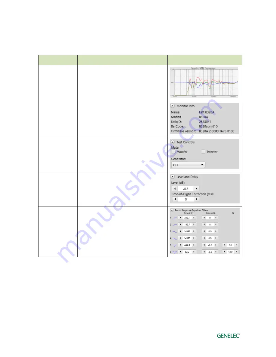
Table 11. Acoustical settings  

Setting 

Description 

View 

Frequency 
response graphs 

Measured frequency response (red), room 
calibration filter (blue), compensated room 
frequency response (green). 


Monitor Info 

Information about the monitor 


Test Controls 

Controls to turn on and off the drivers and the 
test signal generators 


Level and delay 

Sensitivity adjustment (level). Time-of-Flight 
compensation.   


Room Response 
Equalizer Filters 

Low frequency shelving filters (1-2). High 
frequency shelving filters (3-4). Parametric 
notch filters (5-20).  

The number of filters depends on the 
product. For example 82xx Series monitors 
have a different number of parametric filters 
(5-11).  


Level and time-of-flight correction Controls in Monitors and Subwoofer 

SAM monitors contain adjustment of the input sensitivity. This is called the level setting. The input 
sensitivity can by adjusted from the nominal maximum (0 dB) down to – 60 dB.  

The time-of-flight compensation is needed when the monitors are at different distances from the 
listening position. The adjustment range for the time-of-flight is from 0 ms (no additional delay) to 
45…200 ms, depending on the product. This range enables complex reproduction system with 

Summary of Contents for GLM 2.0

Page 1: ...Operating Manual Genelec Loudspeaker Manager GLM 2 0 System ...

Page 2: ...r Example 13 Cabling of the Control Network 15 Downloading and Installing GLM Software 16 Creating a System Layout and Calibrating a System 16 Creating a SAM Monitor Layout 16 Creating a SAM Monitor Group 19 Automatic Calibration Using GLM AutoCal 20 Aligning Subwoofer Phase with GLM AutoPhase 22 Basic Use of GLM 23 Group Tabs 24 System Level Control 24 Mute Dim Preset Level and Bass Management By...

Page 3: ...time of flight correction Controls in Monitors and Subwoofer 43 Room Response Equalizer Controls 44 Sound Character Profiler tool 45 Stand Alone Operation 46 Storing values permanently in monitors and subwoofers 46 Level Control with GLM Volume Controller 46 Connecting the GLM Volume Controller 47 Using a USB power supply 47 Wireless Volume Controller 47 Additional Information 49 GLM display indic...

Page 4: ...lec Smart Active Monitoring SAMTM systems Take a moment to familiarize yourself with the contents of this manual While the use of the products is intuitive there are many options and suggestions in this manual with regards to different types of installations and applications For support contact your local dealer or support genelec com ...

Page 5: ...io input on XLR Digital OUT AES EBU digital audio output on XLR GLM Genelec Loudspeaker Manager Software for setup automatic calibration and management of a monitoring system GLM Network Genelec s proprietary monitoring system control network enabling automatic system setup calibration and control Layout grid A grid on the GLM 2 0 user interface where monitor and subwoofer icons are placed automat...

Page 6: ...igital audio inputs for all monitoring applications Genelec Network Adapter Genelec GLM network adapter 8300 416 connects SAM systems to the USB interface in a computer and operates as the interface for the measurement microphone and as the master for the stand alone volume control Genelec Loudspeaker Manager Software Genelec Loudspeaker Manager GLM software enables setup automatic calibration and...

Page 7: ...woofers and monitors download and install the GLM computer software create a system setup in the GLM software Placing SAM monitors and subwoofers in the monitoring room Try to place monitors and subwoofers in optimum locations in relation to surfaces reflecting audio Aim each SAM monitor towards the listening position This becomes your System Layout 1 Select listening position so that distances fr...

Page 8: ...t is possible to populate both analog and digital inputs and outputs on SAM products GLM 2 0 allows Group configuration to be either analog or digital Note that the 8320 features analog input only The most common audio cablings are introduced next Analog Stereo Example Before cabling turn off the power in all monitors connect audio cables from the audio source to the monitor ANALOG IN Figure 2 Ana...

Page 9: ...dio cable from the audio source to the subwoofer ANALOG IN 1 continue from the subwoofer ANALOG OUT 1 to the monitor ANALOG IN continue connecting all remaining audio input cables to the subwoofer inputs ANALOG IN 2 through to ANALOG IN 5 and from the respective analog outputs to the relevant monitors finally connect the LFE channel from the audio source to the subwoofer LFE IN Figure 4 An example...

Page 10: ...stereo cabling Digital Audio 5 1 with 7200 Series Subwoofer Example Before cabling turn off the power in all monitors and subwoofers An example of the audio cabling for AES EBU digital audio is shown in Figure 6 Any cable carrying the LFE channel can only be connected to the subwoofer input 4 Connect the following XLR digital audio cables Left Right channel pair from the AES EBU output of the audi...

Page 11: ...AL OUT to surround left monitor DIGITAL IN Center LFE channel pair from the AES EBU output of the audio source to the subwoofer DIGITAL INPUT4 connector from the subwoofer DIGITAL OUTPUT4 to the center monitor DIGITAL IN Figure 6 An example of an AES EBU digital audio surround cabling with 7200 Series subwoofer ...

Page 12: ...s position for the required A or B channel selection Connect the following XLR digital audio cables from the AES EBU output of the audio source to the subwoofer DIGITAL INPUT1 input connector from the subwoofer DIGITAL OUTPUT to the right monitor DIGITAL IN from the right monitor DIGITAL OUT to left monitor DIGITAL IN Select the following digital audio channels for the monitor on the left monitor ...

Page 13: ... channel pair from the AES EBU output of the audio source to the subwoofer DIGITAL INPUT2 connector from the subwoofer DIGITAL OUTPUT2 to the surround right monitor DIGITAL IN from the surround right monitor DIGITAL OUT to surround left monitor DIGITAL IN Center LFE channel pair from the AES EBU output of the audio source to the subwoofer DIGITAL INPUT4 connector from the subwoofer DIGITAL OUTPUT4...

Page 14: ...Genelec Loudspeaker Manager GLM 2 0 System Operating Manual page 14 of 55 Figure 8 An example of an AES EBU digital audio surround cabling with SE7261 and digital channel selections for each monitor ...

Page 15: ...ections on the GLM adapter from left to right Connector Use USB type B Connects the GLM adapter to a computer USB interface or USB power supply stand alone volume control Volume 3 5 mm jack Connection for Genelec volume controller Microphone 3 5 mm jack Connection for Genelec calibration microphone GLM Net RJ45 GLM control network connection Terminator RJ45 Return termination for the GLM control n...

Page 16: ...nd are powered on The steps to create a GLM System Setup with a system layout and calibration are 1 create a SAM monitoring system layout 2 define one or more SAM monitoring groups 3 run GLM AutoCal automatic calibration 4 run GLM AutoPhase automatic phase calibration for subwoofers AutoPhase is only available when a subwoofer is included in a group Creating a SAM Monitor Layout To create a layout...

Page 17: ...en the monitor is dropped on the left side it is named as Left 8330A If a monitor has AES EBU digital input it will also get a default AES EBU subframe to be reproduced in the digital group e g when the monitor is dropped to the left side it gets subframe A selected as default Figure 12 An example of an empty monitor stack When you drag the real monitor plays an identification tone and flashes the...

Page 18: ...tarts with 8 SE channels on the Stack They are labeled 1A 1B all the way through 4B However if your SE system only has 2 channels being used in input outputs 1 for stereo 1A and 1 B you would take the next 6 2A thru 4B off the Stack and place them into the Not used in this setup bin Note any SAM monitor that is placed into the Not used in this setup bin Figure 14 cannot be used as part of the curr...

Page 19: ...ct the input signal 2 for the group Analog or AES EBU click on each monitor and subwoofer then edit check the setting 3 for more information see the GLM Advanced Settings the monitor with a green halo is active monitors with yellow halo are not part of the group confirm the group settings by clicking on the Confirm Group button 4 For more detailed information on using and setting up Groups see the...

Page 20: ...cations and defining each location as a new group For example one group can be Engineer Position and another Producer Position Each can have its own calibration Then selecting the group in the GLM 2 0 software quickly loads all acoustic settings specific for each microphone position To calibrate a monitoring group connect the measurement microphone to the GLM network adapter enter the serial numbe...

Page 21: ...Genelec Loudspeaker Manager GLM 2 0 System Operating Manual page 21 of 55 Figure 16 Steps in running the AutoCal automatic system calibration process ...

Page 22: ... at the listening position define the monitor to be aligned with the subwoofer by single clicking on the subwoofer icon first and then the monitor icon this is done for each subwoofer in the group if there are several subwoofers in the group associate every subwoofer with a monitor before proceeding to the AutoPhase calibration start the AutoPhase measurement process by clicking on the calibration...

Page 23: ...ll discuss these in more detail in the section Advanced Use of the GLM Bass Management Bypass button when a subwoofer is used to drive low frequencies to all monitors instead of sending them to a subwoofer Bypass AutoCal to quickly evaluate the effects of AutoCal calibration quick access to monitor and subwoofer settings by double clicking on the monitor and subwoofer icons quick access to GLM Ada...

Page 24: ... setup file so that the levels set before saving the system setup file resume when the system setup file is opened The Preset Level buttons do not change the system level fader setting When a Preset Level button is released the level setting returns the value set in the fader Mute Dim Preset Level and Bass Management Bypass Buttons The states of these buttons are retained for each group The Mute b...

Page 25: ...ou can alternatively save a copy of the current system setup with the File Save as command and then edit this new copy as needed Solo and Mute Pop Up Window Controls Solo means that only the soloed monitors reproduce audio while others are muted Mute means that the selected monitors are muted and do not play audio Solo and mute can be activated for each monitor and subwoofer A pop up menu for thes...

Page 26: ...he Group definition page Duplicate Group adds a new group to the system setup by copying settings of the currently active group Edit Group opens the Group definition page of the currently active group to edit the group settings Delete Group deletes the currently active group from the system setup Edit Acoustic All opens the acoustic editors for all monitors and subwoofers active in the currently a...

Page 27: ...manual Export Setup to Desktop creates zip file to the desktop About show information about GLM including the software version information Displaying monitor and subwoofer data in GLM Several types of information can be displayed in the GLM main window These include input signal level at the monitor and subwoofer inputs 73xx subwoofer 8320 8330 only output level 73xx subwoofer 8320 8330 only tempe...

Page 28: ...s and subwoofers GLM Info Panel GLM Info panel will show the current volume level 1 the current group name 2 and microphone level 3 This panel can be enabled from Setup Show Level Panel menu Access to Monitor and Subwoofer Settings Access to monitor and subwoofer acoustical calibration and settings is available by double clicking on the monitor and subwoofer icons from the GLM Main page You can al...

Page 29: ...ors or close to the listening position have changed It is usually a good idea to take a copy of the current setup file and perform the recalibration in the copy instead of doing it the original setup file This retains both and enables evaluation of the recalibration outcome You can take a copy of your setup file with the File Save as menu command Group Settings Advanced Use A SAM group is the set ...

Page 30: ...for example to synchronize the whole group audio system with a video presentation Access to group settings To access or edit the settings common to a group use the menu command Group Edit Group This displays an editing window where the group settings and the settings for individual monitors and subwoofers can be edited The group settings are shown when you enter the editor You will see the monitor...

Page 31: ...belonging to the group we call this Group OFF and indicate it with a yellow glow around the product in the GLM window and a yellow LED color showing on the actual product Note If using SE7261 and 8130 monitors non SAM monitors 8130 monitors indicates valid digital signal with yellow LED Figure 23 Group signal type selection AES EBU subframe A and B selections For AES EBU digital audio the channel ...

Page 32: ... In Group When the setting is ON this monitor belongs to the current group When the setting is OFF this monitor is not in the group and will not play audio Bass Management Filter frequency This monitor applies the bass management crossover frequency global or a customized crossover frequency individual When Bass Management Bypass is active subwoofer frequencies are reproduced by the monitors Bass ...

Page 33: ...lso assign these as the main channel input or an LFE channel input LFE Channel Gain LFE input can be boosted by 10dB when this gain is not applied in the audio source Bass Management filter frequency This subwoofer applies the bass management crossover frequency global or a customized crossover frequency individual When Bass Management Bypass is active subwoofer frequencies are reproduced by the m...

Page 34: ... audio inputs These subwoofer are fully compatible with GLM 2 0 but naturally cannot accept any analog input directly You can use these subwoofers with analog signals using a separate analog to digital converter Table 5 Group settings for legacy subwoofer with analog input 72xx Series Setting Description View Subwoofer Name Name tag to help identify subwoofer note This subwoofer model has only dig...

Page 35: ...audio source Bass Management filter frequency This subwoofer applies the bass management crossover frequency global or a customized crossover frequency individual When Bass Management Bypass is active subwoofer frequencies are reproduced by the monitors Bass Management setting is individual or global When global is selected all monitors and subwoofers follow the same settings for bass management T...

Page 36: ...nals as SE7261 supports only AES EBU digital audio Table 8 Group settings for SE Monitor 8130 with digital audio input available with SE7261 Setting Description View Monitor Name Name tag to help identify monitor In Group When this setting is ON the monitor belongs to the current group When the setting is OFF the monitor is not in the group and does not play audio AES EBU Digital Channel AES EBU s...

Page 37: ...gital audio inputs This subwoofer is fully compatible with GLM 2 0 but naturally cannot accept any analog input directly You can use these for analog signal with a separate analog to digital converter Table 9 Group settings for SE7261 with analog input Setting Description View Subwoofer Name Name tag to help identify subwoofer note SE7261 cannot be used with analog signals as SE7261 supports only ...

Page 38: ...Bass Management filter frequency This subwoofer applies the bass management crossover frequency global or a customized crossover frequency individual When Bass Management Bypass is active subwoofer frequencies are reproduced by the monitors Bass Management setting is individual or global When global is selected all monitors and subwoofers follow the same settings for bass management This is the de...

Page 39: ...sing the individual setting is an expert feature as the Bass Management Filter for this monitor no longer tracks the selection made in the subwoofer settings Advanced use of AutoCal AutoCal automatic calibration offers you the possibility of using multiple microphone positions MultiPoint in order to determine the system calibration instead of one microphone position located for example at the main...

Page 40: ...esulting frequency response compensations A miniature system layout is shown under the frequency response graph Click on each monitor and subwoofer to review the measurements red curve corrections blue curve and compensated green curve responses in the graph window Note that for standard stereo setups placed in a symmetrical manner equilateral triangle it often makes sense to manually set to 0 the...

Page 41: ...that shows good output from at least the subwoofer and the reference monitor Even better is when there is sufficient output from all monitors at the crossover frequency The output is sufficient when the level in the equalized frequency response is similar to the midrange level and there is no notch in the frequency response close to the crossover frequency The steps to run AutoPhase The steps to r...

Page 42: ...itor if the group has been calibrated The data is color coded The red curve is the measured room response The blue curve is the room equalization filter response The green curve is the equalized room response The equalized room response is recalculated whenever room calibration filters are manually adjusted The sound of the monitor or subwoofer changes immediately when the room calibration filters...

Page 43: ...cy shelving filters 1 2 High frequency shelving filters 3 4 Parametric notch filters 5 20 The number of filters depends on the product For example 82xx Series monitors have a different number of parametric filters 5 11 Level and time of flight correction Controls in Monitors and Subwoofer SAM monitors contain adjustment of the input sensitivity This is called the level setting The input sensitivit...

Page 44: ...o 20 The number and type of room calibration filters depends on the product For example subwoofers contain parametric notch filters only The room response equalization filters are normally set automatically by GLM AutoCal but all settings are available for manual review evaluation and editing if necessary The parameter values can be toggled with the arrow buttons A value can be directly written in...

Page 45: ...rs for each monitor in the selected Group Individual shelving filters may be further adjusted on the Acoustic Settings page if so desired However note that any further modifications to the high frequency HF Shelving filters negates the established profile for that particular monitor and has no effect on the remaining monitors in the Group The Sound Character Profiler tool SCP can be accessed via t...

Page 46: ...store current group settings at current level to SAM monitors enabling the current volume setting and the acoustic calibration settings to be stored permanently in the monitors and subwoofers store current group settings at full level to SAM monitors enabling the full volume setting and the acoustic calibration settings to be stored permanently in the monitors and subwoofers store factory settings...

Page 47: ...ardware level controller input GLM measurement microphone input GLM network and terminator connectors Using a USB power supply The hardware volume controller can also be used for adjusting the sound level when the computer is detached from the GLM adapter When this is done the GLM adapter must be powered with a standard USB power supply The voltage output of the USB supply is 5 VDC To use an exter...

Page 48: ...iring happens during the first 10 seconds after powering up the adapter To pair GLM Adapter and RF remote first press and hold button and then press and hold button The wireless controller can increase and decrease the sound level and turn the system on and off For more information on the wireless volume controller consult your Genelec sales representative Figure 32 Wireless volume controller ...

Page 49: ...gh Flashing Red with text OFFLINE n a Device cannot be found it may be turned OFF or the network is not working Steady red Steady Red Device is muted audio is not passing through Network adapter is connected steady red Network adapter is not found Check USB cabling and status of LED Try to connect to different USB port Microphone is connected to the network adapter Microphone is showing measuremen...

Page 50: ...tion NOTE When using the SE7261 subwoofer with digital input monitors 8130 the monitors LED are not following the actions listed above For example for the 8130 Steady yellow means that the monitor receives a valid digital signal and automatically reproduces this digital signal Steady green means that the monitor automatically reproduces an analog audio signal because a valid digital signal does no...

Page 51: ...ble the use of Griffin Powermate USB Controller with GLM application there is no need to install drivers Griffin Powermate functions can be enabled from Setup Enable USB Controller menu A Powermate setting is individual for each GLM setup file Griffin Powermate functions with GLM are Rotate Clockwise Increase Level Rotate Anti clockwise Decrease Level Press Toggle Level Mute Figure 34 Griffin Powe...

Page 52: ...ay to manually edit acoustic settings Choose a Group to be duplicated From the Group menu choose Duplicate Group This creates a full copy of the selected Group with all acoustic settings included Figure 35 GLM Group tabs How to compare a calibrated and uncalibrated SAM system A Using the Autocal Bypass button located on the main page One can evaluate the benefits of using AutoCal calibration When ...

Page 53: ...n easily be selected by selecting the corresponding group tab in the main GLM window Can analog and digital signal sources be mixed Yes and no One type of signal can be used in one group However it is easy to create two groups one for analog input and another for digital audio input After this switching from one group to the other will select the input signal type How to switch between analog and ...

Page 54: ...e Not used in this setup bin in the Layout page This bin or box is typically used to place unused 8130 channels when defining the number of monitors connected to a SE7261 subwoofer For example if 2 x 8130 are connected to input output 1 on the SE7261 8130 monitor channels 1A and 1B will come off the Stack and be placed onto the Layout Grid The unused monitor channels 2A thru 4B total of 6 should b...

Page 55: ...71 E info genelec com In the U S A Genelec Inc 7 Tech Circle Natick MA 01760 U S A T 1 508 652 0900 F 1 508 652 0909 E genelec usa genelec com In China Beijing Genelec Audio Co Ltd Room 101 1st floor Building 71 B33 Universal Business Park No 10 Jiuxianqiao Road Chaoyang District 100015 Beijing China T 86 10 5823 2014 E genelec china genelec com Genelec Document D0116R003e Copyright Genelec Oy 10 ...

Reviews: