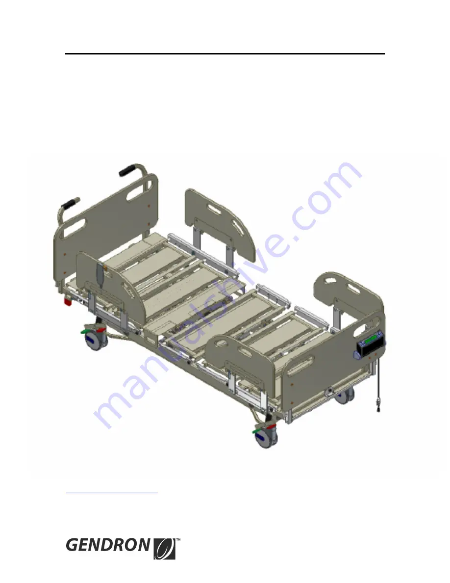
USER MANUAL
Bariatric Acute Care Bed
Model 5148PDX & 5154PDX
Gendron Inc. 520 W. Mulberry Street –Suite 100 Bryan, Ohio 43506
www.gendroninc.com
Page 1: ...USER MANUAL Bariatric Acute Care Bed Model 5148PDX 5154PDX Gendron Inc 520 W Mulberry Street Suite 100 Bryan Ohio 43506 www gendroninc com...
Page 2: ......
Page 3: ...ystem 6 Power Requirements 7 Features Bed and Power Drive System 9 Function Basic Operation Bed and Power Drive System 11 Assembly Instructions 25 Bed and Power Drive System Controls 29 Diagnostics Re...
Page 4: ...4 Parts Locator Bed PATIENT HELPER OPTIONAL HEADBOARD DECK EXTENSION LEFT SIDERAIL FOOT LEFT CPR RELEASE SIDERAIL FOOTBOARD HEAD RIGHT BRAKE STEER DECK EXTENSION DECK EXTENSION PEDAL FOOT RIGHT...
Page 5: ...rts Locator Power Drive System Headboard BRAKE OVERRIDE LEVER WHEEL MOTOR MOTOR BRAKE POWER DRIVE BATTERY CHARGER POWER CORD POWER DRIVE BATTERY CHARGER VARIABLE SPEED FORWARD REVERSE SWITCH ON OFF SW...
Page 6: ...the boom is locked parallel to bed Gently push pull on the patient helper boom to verify that it is locked in position Do not exceed the rated capacity of the patient helper Do not use patient helper...
Page 7: ...re cut frayed or loosely connected Do not use a bed with any missing or damaged parts Do not service this device without first unplugging the power cord and battery Bed sections can move even with pow...
Page 8: ...propriate locations on the bed Keep arms and legs inside the bed at all times Motor brake is not designed to bring the bed to a stop The motor will decelerate to a stop and the brake will engage Confi...
Page 9: ...handset can be selectively locked out by the caregiver control Backlighting facilitates use in low light conditions Construction Constructed entirely of steel solid frame powder coat paint Bed deck Ad...
Page 10: ...eed and direction while operating the bed s power drive system Motor and controller are powered by a 24 volt DC independent circuit Quick release controller connection attached to the headboard 1 1 2...
Page 11: ...head section 2 Raise and lower bed deck 3 Raise and lower knee section 4 Cardio chair bed flat lowers head knee and returns bed to lowest height 5 Trendelenburg reverse Trendelenburg 6 Under bed ligh...
Page 12: ...12 Function Basic Operation Power Drive System On Off Switch Forward Reverse Quick Disconnect...
Page 13: ...ower Drive Control Switch the bed will gradually slow to a complete stop Using Power Drive on incline When stopping bed on incline engage four wheel central lock Disengage Power Drive 1 Bed Must be at...
Page 14: ...14 Caregiver Controls Caregiver controls are located at the foot end of the bed on the side opposite of the rotating scale display Caregiver Controls...
Page 15: ...ld the button of the function desired or Cardio chair position Press and hold the button When the cardio chair button is pushed the head and knee will raise simultaneously to their highest position th...
Page 16: ...to keep the bed tracking in a straight line and to assist in turning corners To activate steer function press down on one of the green Steer pedals Brake Position To set the brakes press down on one...
Page 17: ...17 Push Handles The push handles are located at the head end of the bed on the headboard and are used to facilitate moving the bed Caution Do not move the bed using the side rails Push Handles...
Page 18: ...on To raise siderail grasp top section of rail and lift Allow release pin to snap into the locked position Caution Make sure siderails are securely locked into position to prevent injury Gently pull o...
Page 19: ...ft and right side Caution Always allow head section to fully lower when using CPR release Failure to do so may damage the actuator Note 1 CPR release may not operate unless a patient is lying on the b...
Page 20: ...ve to the desired position Caution Gently push pull on the extension to verify that it is locked in position Caution Ensure that all side extensions are adjusted to the same width Equipment damage may...
Page 21: ...at center of the extension below the footboard and move to the desired position Caution Gently push pull on the extension to verify that it is locked in position Caution Ensure that the extension is a...
Page 22: ...limited time Caution Disconnect battery to prevent discharge during storage Failure to do so will reduce battery life Caution Recharging a fully discharged battery may take up to 24 hours Battery cabl...
Page 23: ...ing Do not allow the patient to use the patient helper unless the boom is locked in the position shown below Failure to do so may result in injury or equipment damage Warning Gently push pull on the p...
Page 24: ...24 IV Pole optional not included IV pole may be used at any one of the 4 corners of the bed Rotate the yellow release mechanism to raise or lower IV pole...
Page 25: ...Assemble patient helper frame to head end of bed frame using 4 bolts and locknuts 2 Lower patient helper boom onto patient helper frame Make sure release pin engages frame and holds boom rotation 3 S...
Page 26: ...26 Headboard 1 Insert headboard mounting tubes into the square sockets at the head end of the bed as shown below Socket Mounting tube...
Page 27: ...uare sockets at the foot end of the bed 2 Connect the two electrical cables Footboard Removal Caution Disconnect the two electrical cables below the footboard before attempting to remove the footboard...
Page 28: ...28 Battery 1 Plug battery into nurse call junction BATTERY NURSE CALL...
Page 29: ...to prevent patient from articulating any bed function Caution Disconnect AC power before unplugging any cables on the control module Failure to do so may result in control module damage Power Drive C...
Page 30: ...30 Diagnostics Repair Bed CONTROL MODULE UNDER BED LIGHT NURSE CALL...
Page 31: ...ontrol module or handset is faulty Replace as required _____________________________________________________________________________ Actuator will not Defective wiring Check wiring between control fun...
Page 32: ...__________________________ Bed sliding on incline Tread wear on wheel Replace wheel if less than 1 16 inch tread is left on wheel Dirty floor Clean floor Defective brake Brake or motor will need to be...
Page 33: ...t to zero Do not press when patient is in the bed Zero Weight Change press and hold to change the displayed weight change to zero Weigh wakes the display Also displays current weight weight change dat...
Page 34: ...he menu button to program the alarm parameters The facility nurse call can be activated by the bed exit alarm if desired by using either the DB37 or 1 4 phono jack located at the head end of the bed N...
Page 35: ...15 high sensitivity 20 30 medium sensitivity 35 45 low sensitivity Bed Exit Alarm on time 30 300 seconds in 30 second increments Alarm will sound for the amount of time desired between 30 300 seconds...
Page 36: ...rations See that All power bed operations work smoothly and stop in any desired position Bed height angle of leg lift and backrest can be adjusted properly Trendelenburg operates smoothly and can be s...
Page 37: ...aning around electrical connections to prevent shock to the person or damage to the electrical components Yearly Inspection and Maintenance Once per Year 1 Check all of the bolts to be sure that none...
Page 38: ...92 5154PX Bed deck adjusts 39 54 x 84 92 Bed deck height adjusts from 16 6 26 6 Head section angle 0 70 Knee angle 0 20 Trendelenburg angle 0 9 Reverse trendelenburg angle 0 9 Siderail length 26 Sider...
Page 39: ...tion and your exclusive remedy under this warranty shall be limited to such repair and or replacement This warranty gives you specific legal rights and you may also have other rights that vary from st...