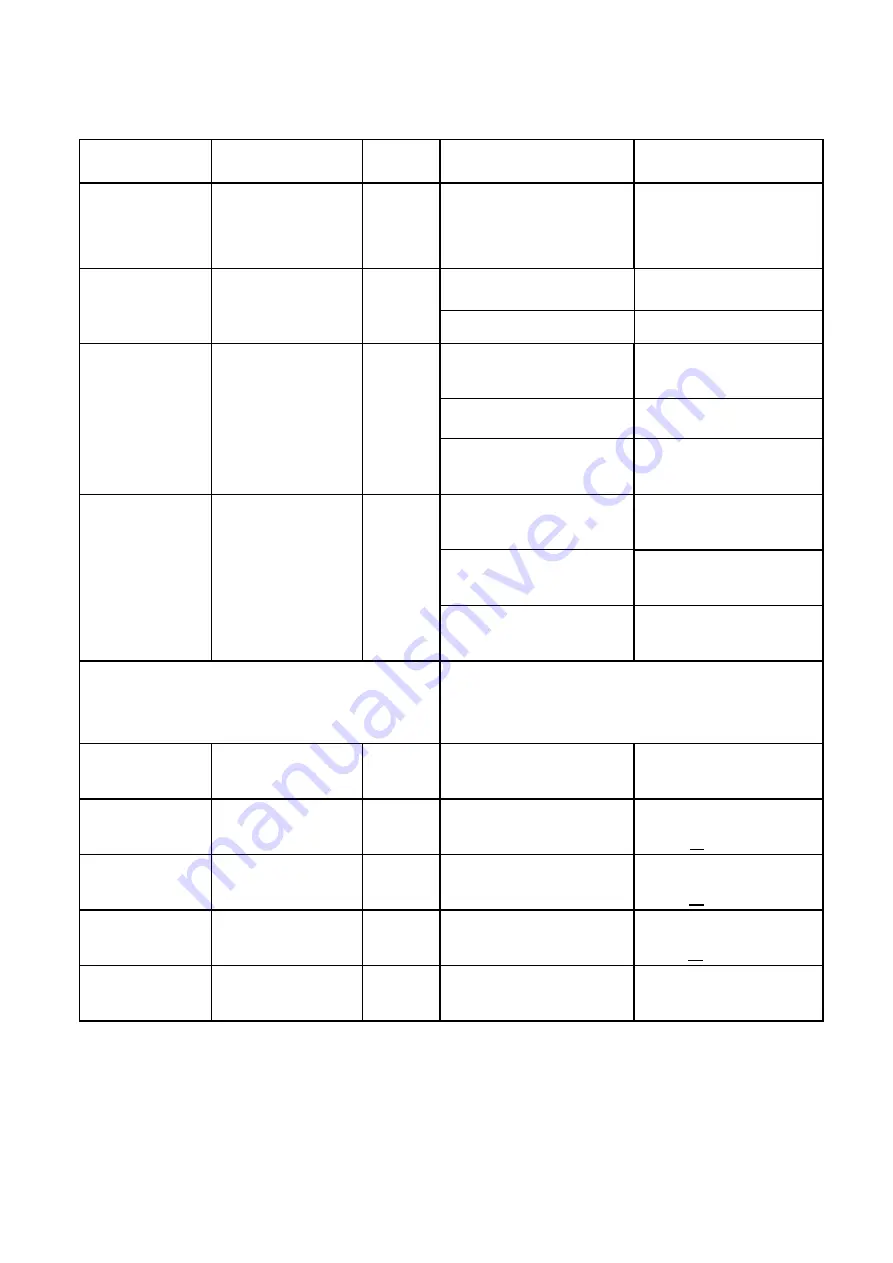
Gemtek WLTGG-122 Quick Installation Manual Download Page 4


LED Indicators   

LED name 

Location 

Color 

LED Behavior 

Status Indication 

LED List 


●●●●●


MAIN power   

○○


○○○○○ 

Blue


ON 

Power On 

OFF 

Power Off 

Ethernet 
status 


○○○○○ 

Orange 

Steady ON 

Detect Ethernet 
Device Connected 

Blinking   

N/A 

OFF 

No Ethernet 
connection 

SIM status 

○○


○○○○○ 

Green 

Steady ON 

SIM DETECTED (with LTE 

connection)


Blinking when 
On-hook 

SIM NO DETECTED / SIM 

NOT INSERTED


OFF 

SIM DETECTED (without 

LTE connection)


LTE Status LED : Link Status 

When CPE is power on, each LED indicates 
each link status ; change upon customer 
requirement   

LTE 1 

○○○


○○○○ 

Blue


Steady ON 

Signal is poor 

SINR < 7dB


LTE 2 

○○○


●●

○○○ 

Blue


Steady ON 

Signal is weak 

  7dB <SINR <11dB


LTE 3 

○○○


●●●

○○ 

Blue


Steady ON 

Signal is Good 

11dB < SINR <18dB


LTE 4 

○○○


●●●●

○ 

Blue


Steady ON 

Signal is very good 

18dB < SINR <23dB


LTE 5 

○○○


●●●●●


Blue


Steady ON 

Signal is Excellent 

SINR>=23dB 


Summary of Contents for WLTGG-122

Page 1: ...LTE CPE Quick installation Guide WLTGG 122 LTE Outdoor CPE...

Page 2: ...1 Contents CONTENTS 1 1 CONNECTORS 2 2 LED INDICATORS 3 3 INSTALLING LTE OUTDOOR CPE 4 4 CONNECTING THE CABLES 7 5 WEB INTERFACE 9...

Page 3: ...for connecting to the PoE adaptor 2 LED indicator inside and SIM card slot for inserting SIM card 3 GPS Antenna The GPS function is optional It will activated base on the different SW customization 4...

Page 4: ...connection Blinking when On hook SIM NO DETECTED SIM NOT INSERTED OFF SIM DETECTED without LTE connection LTE Status LED Link Status When CPE is power on each LED indicates each link status change up...

Page 5: ...ive surfaces Be sure to ground LTE Outdoor CPE with an appropriate grounding wire not included by attaching it to the grounding screw on the unit and to a good ground connection Mounting the ODU Mount...

Page 6: ...her flat washer and the bracket holes and tighten the bolts to the LTE Outdoor CPE 2 Thread the M10 100mm bolt through a spring washer flat washer and the holes of bracket A Attach the bracket A to th...

Page 7: ...wo brackets together Thread the M10 20mm bolt through a spring washer flat washer and the bracket holes 4 Adjust the required angle and lock the screws This is an angle that can be adjusted 10 degrees...

Page 8: ...Insert the Cat5e RJ 45 cable into the sealing gland base and connect it to the RJ 45 connector at the bottom of the ODU labeled Make sure that the connector is completely inserted and tightened Sugges...

Page 9: ...into the gland base Tighten the gland nut Use the dedicated tool for fastening the sealing glands PoE Connection 1 It is assumed that the RJ 45 is already connected to the LTE outdoor CPE Assemble an...

Page 10: ...h is http 192 168 15 1 Step2 Enter ODU administrator login username password to access the web management interface The default username password is admin admin Web management interface Step3 The page...

Page 11: ...r Connect the equipment into an outlet on a circuit different from that to which the receiver is connected Consult the dealer or an experienced radio TV technician for help FCC Caution Any changes or...

Page 12: ...he product shall be installed at a location where the radiating antenna can be kept 30 cm from nearby person in normal operation condition to meet regulatory RF exposure requirement 3 External antenna...

Reviews: