BGS2-E Release Notes
Confidential / Released
BGS2-E_rn_v01.301c
Page 9 of 12
2012-02-08
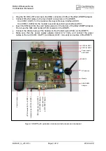
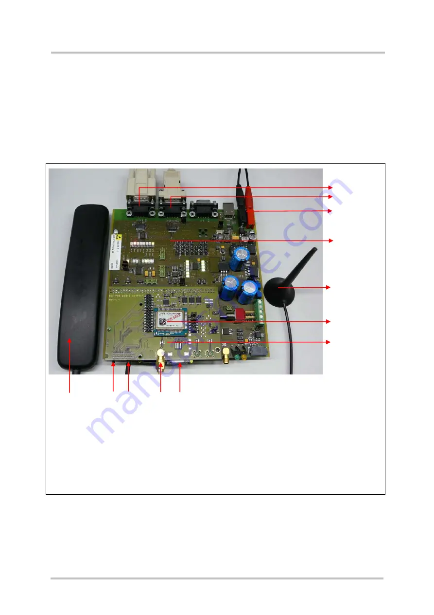
Plug the 50 Ohms RF antenna to the SMA connector (X305) of the BG2-DSB75 Adapter.
Connect RS-232 cables to the 9-pin SubD connectors on the DSB75:
-
Use COM1 (X201) for the module’s first asynchronous interface ASC0.
-
Use COM 2 (X202) for the module’s second asynchronous interface ASC1.
Insert the SIM card into the card holder placed on the bottom of the BG2-DSB75 Adapter.
Do not use the SIM card holder (X503) located on the DSB75.
Connect the Western plug of the handset to the Western jack (X502) on the DSB75.
Make sure that the power supply adapter delivers 12 Volts, and connect the power
cables to the red (X400 = BATT+) and black (X401 = Ground) connectors of the DSB75.
Figure 1: DSB75 with evaluation module and all accessories connected
X202 for ASC1
X201 for ASC0
Power supply
X401/X400
DSB75
RF antenna
Module
BG2-DSB75
Adapter
Votronic handset
IGT/ON switch S421 on DSB75
Handset cable at X502 on DSB75
SMA antenna connector X305
on BG2-DSB75 Adapter
SIM card holder
on BG2-DSB75 Adapter


