background image

www.gemu-group.com

36 / 41

GEMÜ 629 eSyLite

14 Inspection and maintenance

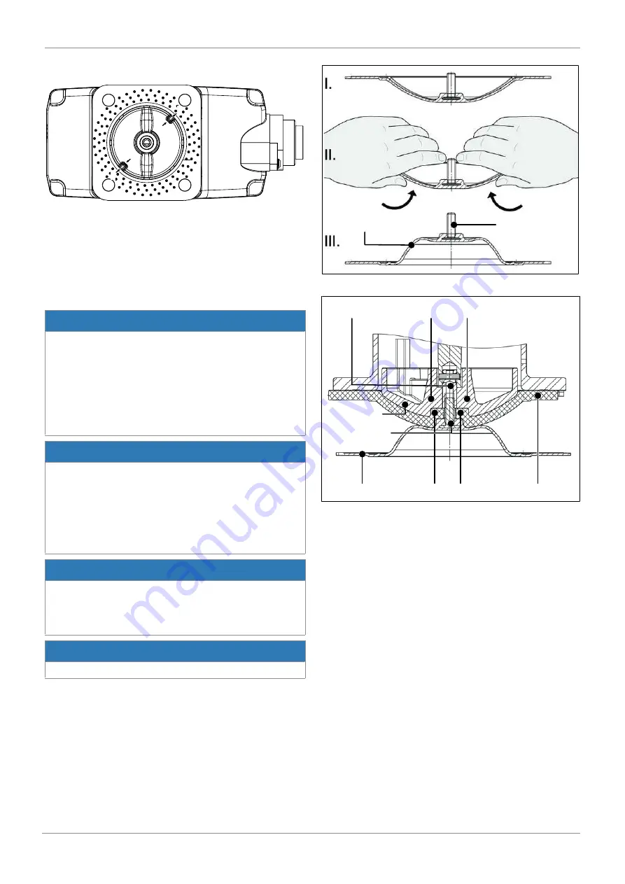
14.4 Mounting the compressor

D

D

C

C

1. Place the compressor loosely on the actuator spindle.
2. Fit recesses 

D

 into guides 

C

.

ð

The compressor must be able to be moved freely between

the guides.

14.5 Mounting the diaphragm

14.5.1 Mounting the convex diaphragm

NOTICE

Fit the diaphragms suitable for the product (suitable for

medium, medium concentration, temperature and pres-

sure). The diaphragm is a wearing part. Check the tech-

nical condition and function of the product before com-

missioning and during the whole term of use. Carry out

checks regularly and determine the check intervals in ac-

cordance with the conditions of use and/or the regulatory

codes and provisions applicable for this application.

NOTICE

If the diaphragm is not screwed into the adapter far

enough, the closing force is transmitted directly onto the

diaphragm pin and not via the compressor. This will

cause damage and early failure of the diaphragm and

leakage of the product. If the diaphragm is screwed in too

far, perfect sealing at the valve seat will not be achieved.

The function of the product is no longer ensured.

NOTICE

Incorrectly mounted diaphragms cause the product leak-

age and emission of medium. In this case, remove the

diaphragms, check the complete valve and diaphragms

and reassemble again proceeding as described above.

NOTICE

The compressor is loose and can fall out.

Diaphragm pin

Diaphragm face

Fig. 6: Inverting the diaphragm face

Compressor

Backing diaphragm

Diaphragm face

Diaphragm boss

Diaphragm pin

Adapter

Recess of compressor

Fig. 7: Screwing in the diaphragm face

1. Move the actuator 

A

 to the closed position.

2. Mount the compressor (see "Mounting the compressor").
3. Check if the compressor is fitted in the guides.
4. Invert the new diaphragm face manually (use a clean, pad-

ded mat with larger nominal sizes).

5. Position the new backing diaphragm onto the compressor.
6. Position the diaphragm face onto the backing diaphragm.
7. Screw diaphragm face tightly into the compressor manu-

ally.

ð

The diaphragm boss must fit closely in the recess of

the compressor.

8. If it is difficult to screw it in, check the thread and replace

damaged parts.

9. When definitive resistance is felt, turn back the diaphragm

until its bolt holes are in correct alignment with the bolt

holes of the actuator.

10. Press the diaphragm face tightly onto the backing dia-

phragm manually so that it returns to its original shape

and fits closely on the backing diaphragm.

11. Align the weir of compressor and diaphragm in parallel.

Summary of Contents for eSyLite 629

Page 1: ...GEM 629 eSyLite Motorized diaphragm valve Operating instructions EN further information webcode GW 629...

Page 2: ...hts including copyrights or industrial property rights are expressly reserved Keep the document for future reference GEM Gebr M ller Apparatebau GmbH Co KG 29 06 2021 www gemu group com 2 41 GEM 629 e...

Page 3: ...nstallation in piping 29 10 1 Preparing for installation 29 10 2 Installation position 30 10 3 Installation with clamp connections 30 10 4 Installation with butt weld spigots 30 10 5 Installation with...

Page 4: ...Diaphragm size Uniform seat size of GEM diaphragm valves for different nominal sizes 1 4 Warning notes Wherever possible warning notes are organised according to the following scheme SIGNAL WORD Type...

Page 5: ...ation and commissioning using trained personnel 4 Provide adequate training for installation and operating personnel 5 Ensure that the contents of the document have been fully understood by the respon...

Page 6: ...associated IT infrastructure actively in crease process reliability Thanks to serialization every valve and every relevant valve component such as the body actuator or diaphragm and even automation c...

Page 7: ...pigot and union nut DIN 11851 6K Flange Flange EN 1092 PN 16 form B face to face dimension FTF EN 558 series 1 ISO 5752 basic series 1 length only for body configuration D 8 Flange ANSI Class 150 RF f...

Page 8: ...tropolished internal external 1508 Ra 0 4 m 15 in for media wetted surfaces in accordance with DIN 11866 H4 mechanically polished internal 1536 Ra 0 4 m 15 in for media wetted surfaces in accordance w...

Page 9: ...11 CONEXO Code Without Integrated RFID chip for electronic identification and traceability C 6 Order data www gemu group com 9 41 GEM 629 eSyLite...

Page 10: ...eries B 5 Valve body material 40 1 4435 F316L forged body 6 Diaphragm material 5M PTFE EPDM two piece 7 Voltage Frequency C1 24 V DC 8 Control module A0 Open Close control economy 9 Surface 1503 Ra 0...

Page 11: ...2 4 2 4 2 4 2 2 3 3 12 3 2 15 3 3 3 8 3 8 3 8 2 2 4 0 3 4 20 3 8 25 15 4 1 4 7 4 7 4 7 7 4 6 5 6 5 20 6 3 7 0 7 0 7 0 4 4 13 2 10 0 10 0 25 13 9 15 0 15 0 15 0 12 6 12 2 16 2 14 0 14 0 40 32 25 3 27 0...

Page 12: ...1 and soft elastomer diaphragm The Kv values for other product configurations e g other diaphragm or body materials may differ In general all diaphragms are subject to the influences of pres sure temp...

Page 13: ...ulation EC No 10 2011 FDA USP Class VI depending on version and or operating parameters 7 5 Mechanical data Protection class IP 65 acc to EN 60529 Actuating speed Max 3 mm s Flow direction Optional In...

Page 14: ...e Clamp MG DN 8 4 0 09 6 0 09 8 0 09 0 15 10 0 09 0 21 0 18 15 0 09 0 18 10 10 0 30 0 33 0 30 12 15 0 30 0 35 0 43 20 0 30 0 43 25 15 0 62 0 50 0 32 0 71 1 85 0 75 20 0 58 0 60 0 34 0 78 2 35 0 71 25...

Page 15: ...ize 8 0 5 A MG 10 0 5 A MG 25 1 3 A MG 40 2 3 A Starting current max imum current Diaphragm size 8 approx 2 4 A MG 10 approx 2 4 A MG 25 approx 2 4 A MG 40 approx 4 5 A Standby current con sumption ap...

Page 16: ...B MG A A1 B B1 B2 B3 8 211 0 82 0 59 5 134 5 115 0 82 0 10 192 0 63 0 59 5 134 5 115 0 82 0 25 204 0 75 0 59 5 134 5 115 0 82 0 40 228 0 91 0 80 0 167 0 147 5 94 5 Dimensions in mm MG diaphragm size C...

Page 17: ...icator A BZ2 AZ1 AZ2 BZ1 MG A AZ1 AZ2 BZ1 BZ2 8 256 0 72 0 61 0 30 0 40 0 10 237 0 72 0 61 0 30 0 40 0 25 249 0 72 0 61 0 30 0 40 0 40 273 0 72 0 61 0 30 0 40 0 Dimensions in mm MG diaphragm size GEM...

Page 18: ...1 5 1 0 1 5 2 0 1 6 20 3 4 25 0 22 0 22 0 23 0 24 0 26 9 19 0 120 0 1 5 1 0 1 5 2 0 1 6 25 1 25 0 28 0 28 0 29 0 30 0 33 7 19 0 120 0 1 5 1 0 1 5 2 0 2 0 40 32 1 25 0 34 0 34 0 35 0 36 0 42 4 26 0 15...

Page 19: ...21 3 12 5 108 0 1 5 1 6 25 15 1 2 25 0 19 0 21 3 13 0 120 0 1 5 1 6 20 3 4 25 0 23 0 26 9 16 0 120 0 1 5 1 6 25 1 25 0 29 0 33 7 19 0 120 0 1 5 2 0 40 32 1 25 0 35 0 42 4 24 0 153 0 1 5 2 0 40 1 25 0...

Page 20: ...2 77 1 65 3 38 40 32 1 25 0 42 2 42 2 42 2 26 0 153 0 2 77 1 65 3 56 40 1 25 0 38 10 48 3 48 3 48 3 26 0 153 0 1 65 2 77 1 65 3 68 Connection type spigot ASME BPE code 59 1 investment casting materia...

Page 21: ...1 2 2 80 1 2 40 32 1 25 0 31 8 42 7 33 7 26 0 153 0 1 2 2 80 1 2 40 1 25 0 38 1 48 6 38 0 26 0 153 0 1 2 2 80 1 2 Connection type spigot SMS code 37 1 investment casting material code C3 2 MG DN NPS...

Page 22: ...l code 37 2 MG DN NPS H H1 L n R SW 2 t 8 8 1 4 19 0 9 0 72 0 6 G 1 4 18 0 11 0 10 12 3 8 25 0 13 0 55 0 2 G 3 8 22 0 12 0 15 1 2 30 0 15 0 68 0 2 G 1 2 27 0 15 0 25 15 1 2 28 3 14 8 85 0 6 G 1 2 27 0...

Page 23: ...1 2 27 0 14 0 20 3 4 34 0 17 3 85 0 6 0 NPT 3 4 32 0 14 0 25 1 43 0 21 8 110 0 6 0 NPT 1 41 0 17 0 40 32 1 52 0 26 3 120 0 8 0 NPT 1 50 0 17 0 40 1 57 0 28 8 140 0 8 0 NPT 1 55 0 17 0 Dimensions in m...

Page 24: ...118 0 Rd 34 x 1 8 25 15 1 2 16 0 19 0 118 0 Rd 34 x 1 8 20 3 4 20 0 19 0 118 0 Rd 44 x 1 6 25 1 26 0 19 0 128 0 Rd 52 x 1 6 40 32 1 32 0 26 0 147 0 Rd 58 x 1 6 40 1 38 0 26 0 160 0 Rd 65 x 1 6 Dimens...

Page 25: ...34 x 1 8 25 15 1 2 16 0 19 0 116 0 Rd 34 x 1 8 20 3 4 20 0 19 0 114 0 Rd 44 x 1 6 25 1 26 0 19 0 127 0 Rd 52 x 1 6 40 32 1 32 0 26 0 147 0 Rd 58 x 1 6 40 1 38 0 26 0 160 0 Rd 65 x 1 6 Dimensions in m...

Page 26: ...140 0 180 0 180 0 28 0 28 7 24 0 26 0 100 0 19 0 4 40 1 150 0 200 0 200 0 28 0 33 0 26 0 26 0 110 0 19 0 4 Dimensions in mm MG diaphragm size n number of bolts 1 Connection type Code 8 Flange EN 1092...

Page 27: ...16 0 19 0 69 9 15 9 4 25 1 110 0 160 0 19 0 23 0 19 0 19 0 79 4 15 9 4 40 32 1 115 0 180 0 28 0 28 7 24 0 26 0 88 9 15 9 4 40 1 125 0 200 0 28 0 33 0 26 0 26 0 98 4 15 9 4 Dimensions in mm MG diaphra...

Page 28: ...5 0 12 5 88 9 108 0 20 3 4 15 75 15 75 25 0 25 0 12 5 101 6 117 0 25 20 3 4 15 75 15 75 25 0 250 19 0 101 6 117 0 25 1 22 10 22 10 50 5 50 5 19 0 114 3 127 0 40 40 1 34 80 34 80 50 5 50 5 26 0 139 7 1...

Page 29: ...same room as GEM products and their spare parts 10 Installation in piping 10 1 Preparing for installation WARNING The equipment is subject to pressure Risk of severe injury or death Depressurize the p...

Page 30: ...nections Fig 1 Clamp connection NOTICE Gasket and clamp The gasket and clamps for clamp connections are not in cluded in the scope of delivery 1 Keep ready gasket and clamp 2 Carry out preparation for...

Page 31: ...eliv ery Only use appropriate sealing material NOTICE Connector elements The connector elements are not included in the scope of delivery Only use connector elements made of approved materi als Observ...

Page 32: ...l connection Connection X1 1 3 2 6 5 4 7 pin plug Binder type 693 Pin Signal name 1 24 V supply voltage 2 GND 3 Digital input OPEN 4 Digital input CLOSED 5 n c 6 n c 7 n c Preferred direction when bot...

Page 33: ...ility and guarantee will be void Only operate the manual override by hand because there is no mechanical stop 1 2 1 Remove the sealing plug 2 from the actuator cover 1 using an appropriate tool 3 OPEN...

Page 34: ...d for the operating conditions Voltage is not connected Connect voltage Cable ends incorrectly wired Wire cable ends correctly The product doesn t close or doesn t close fully The actuator design is n...

Page 35: ...guidelines 3 Shut off plant or plant component 4 Secure plant or plant component against recommission ing 5 Depressurize the plant or plant component 6 Actuate GEM products which are always in the sam...

Page 36: ...ectly mounted diaphragms cause the product leak age and emission of medium In this case remove the diaphragms check the complete valve and diaphragms and reassemble again proceeding as described above...

Page 37: ...elements may vary depending on the dia phragm size and or valve body version 4 Move the actuator A to the closed position 5 Open actuator A approx 20 6 Fully tighten the bolts with nuts diagonally 7...

Page 38: ...the specific technical documentation has been compiled in accordance with part B of Annex VII The manufacturer or his authorised representative undertake to transmit in response to a reasoned request...

Page 39: ...and Industrie Service GmbH Number 0035 Certificate no 01 202 926 Q 02 0036 Conformity assessment procedure Module H1 Technical standard used AD 2000 Note for products with a nominal size DN 25 The pro...

Page 40: ...declare that the product listed below complies with the safety requirements of the EMC Directive 2014 30 EU Description of the product GEM 629 Technical standards used Interference resistance DIN EN 6...

Page 41: ...GEM Gebr M ller Apparatebau GmbH Co KG Fritz M ller Stra e 6 8 74653 Ingelfingen Criesbach Germany Phone 49 0 7940 1230 info gemue de www gemu group com Subject to alteration 06 2021 88767818 88767818...

Reviews: