gefran 1600P Installation And Operation Manual Download Page 10

Programmer functions

7 • USING THE PROGRAMMER

There are up to 12 (16*) steps arrangeable in 4 programs. A program step contains the ramp and the hold time. Ramp times and hold times are programmable with a time base 

selected as 99h59m or 99m59s. Time base accuracy is greater than 4 secs every 10 hours.

Program selection from faceplate, digital input or serial line.

Program control from keys, digital inputs (START/STOP, RESET, end of program), serial line or events AL1/AL2/AL3.

Program stopping and restarting modes:

- from digital input; from “Raise” (START) key, “Lower” (STOP) key or “M/A” (RESET) key in absence of other enablings

- from state of alarms (ON = START)

- different modes of restarting after a power failure

• from setpoint prior to power failure

• from value of process variable at power-up

• with search for best setpoint forward/backward in time

• awaiting a start

In the STOP phase, it is possible to change:

- current setpoint

- current step time

- program number

- step number

- phase or segment (ramp or hold)

The clearance input and event outputs assigned to an individual step. Programmed input conditions are scanned at the beginning of every step. 

If satisfied, execution begins with updating of assigned outputs and restart of time base.

Indication of end of program, with or without forcing of control output.

Setting a tolerance band for setpoint: if the process variable is outside the band, the time base stops (Hbb - Hold back band alarm).

Secondary setpoint with the same time base to manage a slave controller using retransmission output W1 or W2.

Full functional modularity, with easy exclusion of functions not needed. Up to 4 parameter groups to control and limit power, selectable by single segment (ramp and/or hold).

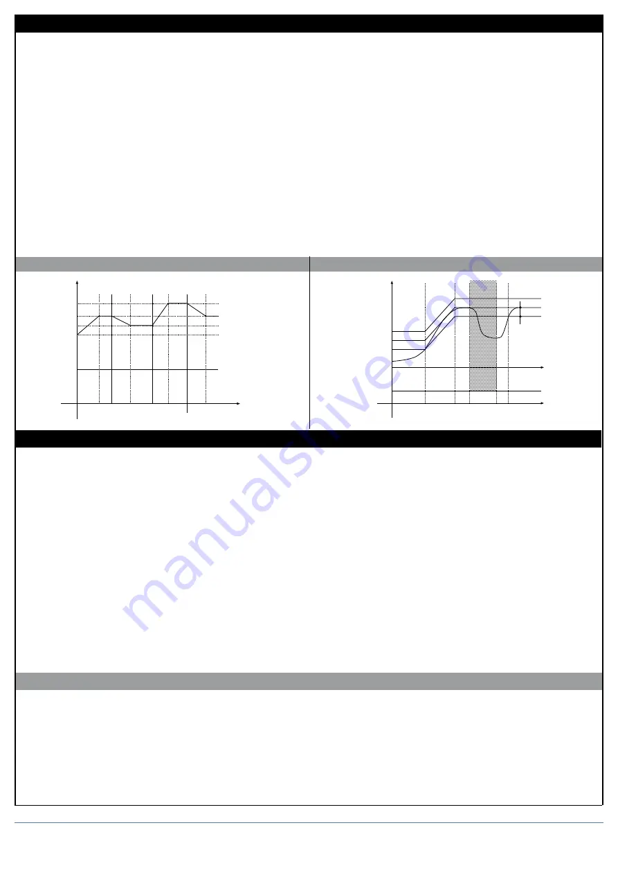
Function Hbb example (holding band)

Program example

6 • PROGRAMMER

The unit combines the functions of a single loop controller and programmer.

The programmer function lets you run a program as a series of steps, each of which has two segments:

 a ramp

 a hold.

Every step has its associated data:

• SPs: a setpoint value

• rPt: ramp time from 0.0 to 99h59m (time base in h. m.) or 99m59s (time base in m. s.); set a time that gives a faster or slower variation depending on the 

initial value and on the final setpoint.

• Sot: hold time from 0.0 to 99h59m (time base in h. m.) or 99m59s (time base in m. s.).

• Hbb: tolerance band, symmetrically positioned above and below the setpoint, and referenced to the main input or the auxiliary input.

• Eur: outputs 1...4; combination codes for outputs (0-15) programmable for the ramp phase.

• EuS: outputs 1...4; combination codes for outputs (0-15) programmable for the hold phase.

• iPt: active inputs (ON) as clearance for execution.

• SLS: slave setpoint to transmit to a slave controller with the same time base.

• GrP: parameter groups to control and limit power (up to 4), selectable by single segment.

There are 12 (16*) program steps available that can make up a maximum of 4 programs.

Examples of arrangements:

2 program of 8 and 4 steps; 4 programs of 3 steps; 2 programs of 6 steps; etc...

It is important to remember that the parameter Sty defines enabling of Hbb (on the ramp, in hold, or both) and the reference value (PV or aux input).

(*) Alternative to custom linearization function (see parameter SP.Pr, Hrd menu).

Temperature

Step 5

Step 6

Step 7

Step 5

I° CYCLE

II° CYCLE

tr5

tp5

tr6

tp6

tr7

tp7

tr5

tp5

Start

SP06

SP05

SP07

Time

t

off

t

on

t

t

Temperature

Program recovery

S.P.

Ti

tw1

tr

tp1

tw2 tp2

tp = tp1 + tp2

Hbb

Power

Off

Time

tw = waiting time

tr = ramp time

tp = hold time

Variation of the local setpoint when the program is stopped will restart the current step, keeping the same ramp time.

If the unit is switched off and then switched on, the program can continue or can start again at the first step. 

Or it can search for the step that has the setpoint closest to the PV (see Pty parameter in ProG configuration to define restart conditions).

STOP/START switching at end of program resets and restarts the program.

Fast simulation of program:

A selected program can easily be checked by running it in fast simulation mode.

To do this, set code Pty +64 in the ProG menu.

The program runs with the ramp and hold times limited to 20 and 10 seconds, respectively. Lower values entered are accepted.

10

80090G_MHW_1600-1800P_04-2013_ENG

Summary of Contents for 1600P

Page 1: ...range with or without decimal point PTC type on request DIN 43760 Pt100 JPT100 990Ω 25 C Max line resistance for RTD 20Ω Safety detection of short circuit or opening of probes LBA alarm HB alarm C F selection configurable from faceplate Linear scale ranges 1999 to 9999 with configurable decimal point position Thermocouples IEC 584 1 J K R S T B E N Ni Ni18Mo L NiCr CuNi Cold junction error 0 1 C C...

Page 2: ...r supply isolated 1500V 10 24Vdc max 30mA short circuit protection 9 5 18 20 19 21 22 Out2 AL1 Out1 Main C 32 W1 Transmitter supply GND Vt 1 2 3 4 5 6 7 8 9 10 11 24 25 26 27 28 29 30 31 32 33 22 21 20 19 18 17 16 15 14 13 12 1800 1600 NC NC NC NO NO NO C C PWR 3 1 2 T 3 1 2 T Key Function defined with but 2 parameter M A key Function defined with butt parameter PV Display Indication of process va...

Page 3: ...eep the F key pressed to scroll the menus Release the F key to select the displayed menu Press the F key to access the parameters Keep the F key pressed to exit any menu Keep F Auto Man keys pressed for 2 sec on any menu to go immediately to level 1 display S3 ON Current setpoint display only LEVEL 1 MENU PASS NO SI Hrd U CAL S4 ON YES NO Custom menu Password User calibration Protection code The a...

Page 4: ...ON 11 ON ON OFF ON 12 OFF OFF ON ON 13 ON OFF ON ON 14 OFF ON ON ON 15 ON ON ON ON S step hold events Step S advanced through digital input function When digital inputs have state set in this function program automatically advances to next step otherwise it waits at end of previous step function is enabled through SP Pr parameter on Hrd menu d i F 1 and or d i F 2 set to 12 Hold Back Band value sy...

Page 5: ... control Ctrl 14 has been selected s tvn CFG Enabling self tuning autotuning softstart CFG Control parameters 15 S tun Continuos Self tuning Softstart autotuning 0 NO NO NO 1 YES NO NO 2 NO YES NO 3 YES YES NO 4 NO NO YES 5 YES NO YES 6 7 8 WAIT NO NO 9 GO NO NO 10 WAIT YES NO 11 GO YES NO 12 WAIT NO YES 13 GO NO YES Note 1 Active S tun functionS reset when switching from Automatic to Manual Propo...

Page 6: ...o local setpoint 2 digital absolute from serial line 3 digital relative to from serial line local setpoint PROBE TC SEnS 0 tYPE Probe type Scale Scale range max Scale range max C F without decimal point with decimal point 0 PTC 990Ω C 55 120 55 0 120 0 1 PTC 990Ω F 67 248 67 0 248 0 2 PTC 990Ω C Custom scale 3 PTC 990Ω F Custom scale tYPE Signal type Scale Max scale range 0 0 50mV linear 1999 9999...

Page 7: ...lla corrente di carico inferiore alla soglia impostata nel tempo di ON dell uscita di controllo 1 Uscita relè logica allarme attivo ad un valore della corrente di carico superiore alla soglia impostata nel tempo di OFF dell uscita di controllo 2 Allarme attivo se una delle funzioni 0 e 1 è attiva OR logico tra le funzioni 0 e 1 3 Per uscita continua di riscaldamento 7 Per uscita continua di raffre...

Page 8: ... analogue repetition signal output 2 Out W2 Assignment of signal or reference value PV SP SP PROG DEV DEV IN AUX HEAT COOL AL1 AL2 AL3 serial line value 79 80 81 Hrd sp pr hrd i hrd 2 Hrd Hardware configuration Installation of aux input digital inputs serial interface Installation of relay logic outputs MAIN AL1 AL2 AL3 and analogue outputs W1 W2 16 to enable analogue output W1 32 to enable analog...

Page 9: ...e 0 10V 2 10V 6 Custom 10V 7 Custom max 50mV Selection of probe type for main input 16 disable function in configuration menu only for butt parameters 8 to enable main input curve 4 point correction alternative to custom linearization See description in Main Input Correction Function section 16 to disable averaging filter on sampled value available from software release 3 05 8 to disable averaging...

Page 10: ...int value rPt ramp time from 0 0 to 99h59m time base in h m or 99m59s time base in m s set a time that gives a faster or slower variation depending on the initial value and on the final setpoint Sot hold time from 0 0 to 99h59m time base in h m or 99m59s time base in m s Hbb tolerance band symmetrically positioned above and below the setpoint and referenced to the main input or the auxiliary input...

Page 11: ...d by intercepting the setpoint profile point B1 If interception is not possible as in the case of variable at PV1 program restart occurs at the current time and setpoint If the Hbb control is enabled the programmer time base remains stopped until the variable re enters the set tolerance band symmetrically placed around the setpoint PV1 1 2 3 4 t1 t2 A1 A B1 B PV Set point Step 0 time Display Modif...

Page 12: ...he output is in OFF state The alarm is reset automatically when alarm conditions have been cleared If AL Hb is set at 0 both types of HB alarm are disabled and the assigned relay is de energized The load current reading is displayed by selecting InP2 level 1 NOTE ON OFF times refer to the cycle time set for the selected output Alarm Hb_F 3 7 for analog output is ON when the load current is lower t...

Page 13: ...ional band at 0 1 with on off type setting C Switch to automatic and observe the behavior of the variable It will be similar to that in the figure D The PID parameters are calculated s follows Proportional band Peak P B x 100 V max V min V max V min is the scale range Integral time It 1 5 x T Derivative time dt It 4 E Switch the unit to manual set the calculated parameters Return to PID action by ...

Page 14: ...mmer model the program is in STOP if self tuning is activated when the unit is switched on 14 SELF TUNING 15 AUTO TUNING PID parameters cannot be set if the self tuning function is enabled The function can be one of two types permanent or one shot The first continuously measures system oscillations to find the optimum PID values to reduce such oscillations It does not engage if the oscillations dr...

Page 15: ...n is applied to linear scales 50mv 10V 20mA Pot The four values are set on the Lin menu as follows A1 St100 B1 St01 A2 St02 B2 St03 Setting is limited to the defined scale LoS HiS on InP menu The offset function oFt parameter on InP menu remains enabled Limits B1 always greater than A1 B1 A1 at least 25 of full scale of selected probe Example Sens 9 TyPE 0 Pt100 natural scale 200 600 dPS 0 LoS 0 H...

Page 16: ...an isolation transformer be used only for the devices connecting the screen to ground it is important for the electrical system to have a good ground connection voltage between neutral and ground must not exceed 1V and resistance must be less than 6Ohm if the supply voltage is highly variable use a voltage stabilizer for the device use line filters in the vicinity of high frequency generators or a...

Reviews: