Gefen EXT-WRS232 User Manual Download Page 16

12

How to Connect the Wireless RS-232 Extender

1.  Connect a RS-232 cable from the controlling device to the RS-232 input on 

the Sender unit using the supplied RS-232 serial cable.

2.  Connect another RS-232 cable from the RS-232 output connector on the 

Receiver unit to the RS-232 port on the device you wish to control.

3.  Connect the included 5V DC power supplies to the power receptacles on 

both the Sender unit and Receiver unit.

4.  Refer to the section below on how to set the baud rate and using the tact 

switches for configuring RS-232 device assignment.

How to Operate the Wireless RS-232 Extender

Setting the Baud Rate

RS-232 devices will function at different baud rates.  It is important that the 

correct baud rate be set on both the Wireless RS-232 Sender unit and Wireless 

RS-232 Receiver unit to establish successful communication between the RS-

232 controller (host) and the RS-232 device you wish to manage (client).

On the bottom of both the Sender unit and Receiver unit is a bank of two (2) 

DIP switches.  You will need to remove the piece of silver adhesive tape on the 

bottom of the units to expose the DIP switch bank.  DIP2 controls the baud rate.  

Setting DIP2 to the ON position sets the baud rate to 19200bps.  Set DIP2 to the 

OFF position if your RS-232 devices run at 9600bps.  Make sure that both the 

Receiver unit and the Sender unit have DIP2 set to the same position.
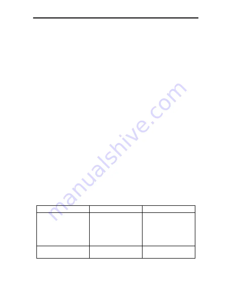
DIP Switch Guide

CONNECTING AND OPERATING THE

WIRELESS RS-232 EXTENDER

DIP switch / State 

ON 

OFF 

Turns a device into 

network mode. While 

in this mode the device 

will communicate 

only with associated 

devices. 

Turns off the network 

mode. The device will 

communicate with any 

other device. 

2

Sets baud rate to 19200 

[Bd]. 

Sets baud rate to 9600 

[Bd]. 

Summary of Contents for EXT-WRS232

Page 1: ...www gefen com Wireless RS232 Extender EXT WRS232 User Manual...

Page 2: ......

Page 3: ...00 Nordhoff St Chatsworth CA 91311 www gefen com support gefen com Notice Gefen LLC reserves the right to make changes in the hardware packaging and any accompanying documentation without prior writte...

Page 4: ...t Panel Description 8 Receiver Unit Panel Layout 9 Receiver Unit Panel Descriptions 10 Sender Unit Receiver Unit Layout Bottom 11 Sender Unit Receiver Unit Descriptions Bottom 12 16 Connecting And Ope...

Page 5: ...your computer without the hassle of using RS 232 cables Control your favorite Gefen products or any devices that use the RS 232 serial control interface How It Works Simply connect the Gefen Wireless...

Page 6: ...no guarantee that interference will not occur in a particular installation If this equipment does cause harmful interference to radio or television reception which can be determined by turning the equ...

Page 7: ...interference that may cause undesired operation of the device To reduce potential radio interference to other users the antenna type and its gain should be so chosen that the equivalent isotropically...

Page 8: ...power connector Two selectable baud rates 9600 or 19200 please see page 12 for details Unlimited number of nodes when using multiple Sender units and Receiver units in a wireless RS 232 network one to...

Page 9: ...le Sender units can also operate simultaneously allowing greater flexibility in a wireless RS 232 solution Please see page 13 for details on setting up a wireless RS232 network Although the Sender uni...

Page 10: ...6 Front Panel Back Panel Sender unit panel Layout 4 3 2 1...

Page 11: ...ccepts the female end of an RS 232 serial cable 2 Power LED The LED will glow red when power is applied to the unit 3 Antenna Transmits RS 232 data to the Receiver unit 4 5V DC Power Receptacle This p...

Page 12: ...8 Receiver unit panel Layout 1 Front Panel 3 Back Panel 2 4...

Page 13: ...port accepts the male end of an RS 232 serial cable 2 Power LED The LED will glow red when power is applied to the unit 3 Antenna Receives RS 232 data from the Sender unit 4 5V DC Power Receptacle Th...

Page 14: ...10 10 Underneath Receiver unit Underneath Sender unit SENDER Receiver unit LAYOUT BOTTOM 6 5 2 3 1 4...

Page 15: ...Switch Used to pair a Receiver unit with a Sender unit 4 Sender Unit Unit L Tact Switch Used to pair a Receiver unit with a Sender unit 5 Sender Unit Unit DIP Switch Bank Used to switch between networ...

Page 16: ...er unit and Wireless RS 232 Receiver unit to establish successful communication between the RS 232 controller host and the RS 232 device you wish to manage client On the bottom of both the Sender unit...

Page 17: ...2 Device from Different Locations 1 Using the DIP switch chart as a guide set DIP switch 2 to the baud rate used by the devices you wish to control All Wireless RS 232 Receiver units must be set to th...

Page 18: ...evices from a Single Location 1 Using the DIP switch chart set DIP switch 2 to the correct baud rate used by your RS 232 devices Since only one Receiver unit will be controlling multiple Receiver unit...

Page 19: ...ver units 1 Using the DIP switch chart as a guide set DIP switch 2 to the correct baud rate used by each RS 232 device Since you will be controlling separate RS 232 devices ensure each RS 232 Sender u...

Page 20: ...ent during the learning process 7 Once each Sender unit Receiver unit pair has been configured you can control several RS 232 devices from a single location Erasing the Electronic Serial Numbers ESNs...

Page 21: ...4 GHz RS 232 Sender unit DB 9 F RS 232 Receiver unit DB 9 F Power Supply 5V DC Locking Sender unit Receiver unit Power Consumption 100mW max Dimensions 1 2 W x 3 8 D x 1 2 H Shipping Weight 2 lbs spe...

Page 22: ...d 1 Proof of sale may be required in order to claim warranty 2 Customers outside the US are responsible for shipping charges to and from Gefen 3 Copper cables are limited to a 30 day warranty and cabl...

Page 23: ......

Page 24: ...20600 Nordhoff St Chatsworth CA 91311 1 800 545 6900 818 772 9100 fax 818 772 9120 www gefen com support gefen com Rev A5 Pb MA WRS232...

Reviews: