


10
ADJUSTING THE HDMI CAT-5 IR EXTENDER
Boost
The boost setting will affect the amount of pre-emphasis that will be applied to
the video signal. This setting is located on the HDMI CAT-5 IR Extender sending
unit and has 4 distinct strength settings. This setting is mainly related to the
distance of CAT-5, CAT-5e or CAT-6 cabling used but is also affected by the
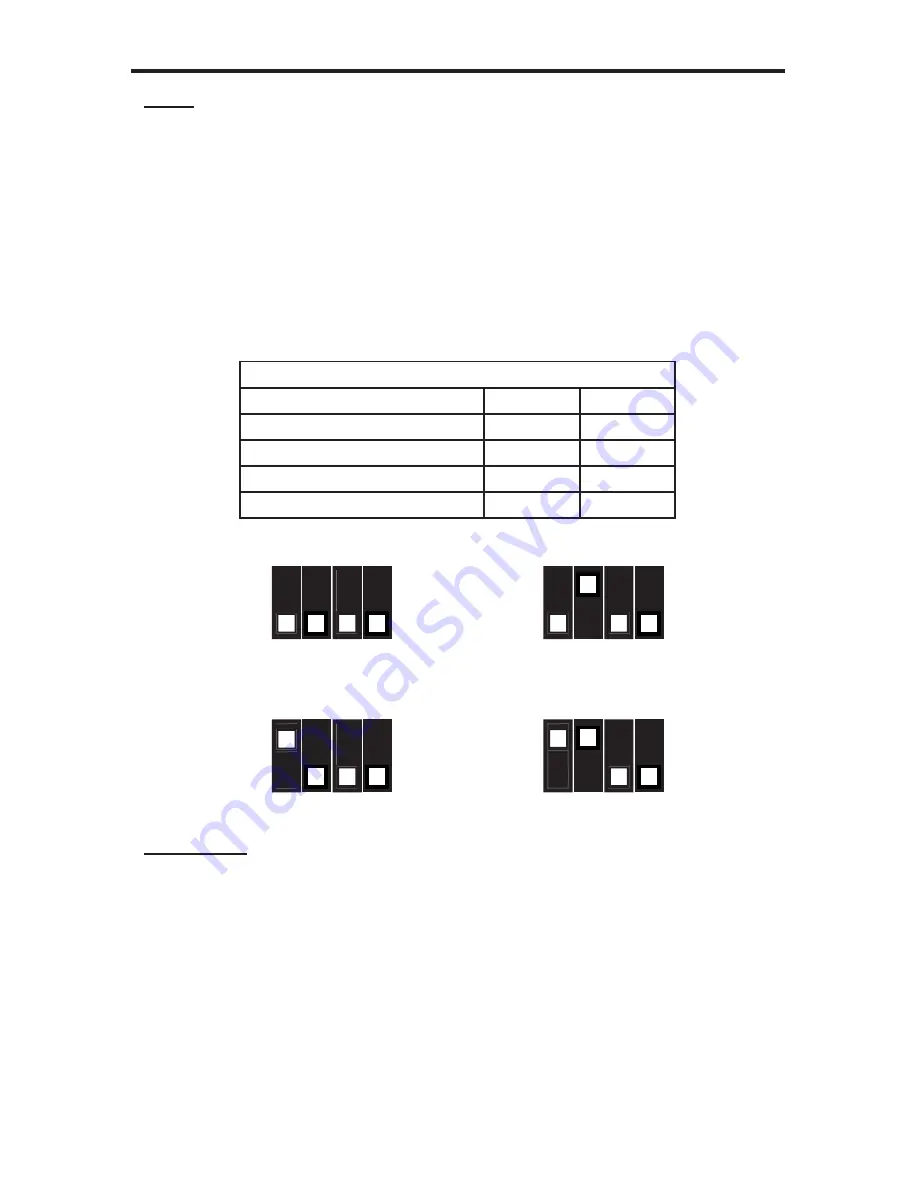
quality and skew of the cabling. The boost settings are set using a bank of DIP
switches on the underside of the HDMI CAT-5 IR Extender sending unit. The
bank of 4 DIP switches is located underneath a piece of metallic colored tape.
Remove this tape to expose the DIP switches. Only DIP switches 1 and 2 are
used on this bank. DIP switches 3 and 4 are not used. The default position of all
DIP switches are OFF (no boost). Please see the table and illustration below for
confi guration options.
Sender Dip Switch Settings
Setting
Switch 1
Switch 2
No Boost (Default)
OFF
OFF
Medium Boost
OFF
ON
High Boost
ON
OFF
Very Low Boost
ON
ON
Equalization
The equalization setting will tune the signal effectively eliminating any video
noise. This setting is located on the HDMI CAT-5 IR Extender receiving unit
in the form of a Trim Pot adjustment dial. To adjust the equalization follow the
instructions below.
1. Insert a small fl at head tool into the Trim Pot on the receiver unit.
2. Turn the trim pot in a clockwise fashion until it comes to a stop. Do not force
the trim pot beyond this point. Doing so may break the trim pot.
3. Slowly turn the trim pot counter-clockwise in millimeter increments until the
image stabilizes and all video noise is eliminated.
4. Carefully remove the adjustment tool.
No Boost (default)
High Boost
Medium Boost
Very Low Boost
OFF
OFF
ON
ON
1 2 3 4
1 2 3 4
OFF
OFF
ON
ON
1 2 3 4
1 2 3 4


