GEKCO DIGITAL CLOCK P/N CLK036 ASSEMBLY & OPERATION MANUAL
14
REV 1.0
GEKCO INC.
( )
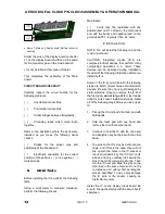
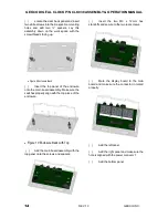
Locate the clear back panel and insert
two white screws into their respective mounting
holes and add two
¼” spacers. Lay this
assembly down on the work space with the
screw threads facing up.
Figure 9 Enclosure Back
( )
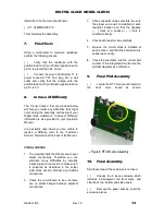
Insert the top panel of the enclosure
onto the main board assembly. Make sure the
switches properly align with the top piece of the
enclosure.
Figure 10 Enclosure Back with Top
( )
Add the main board assembly with the
top panel on to the screws and spacers.
( )
Insert the two M3 x 12mm hex
standoffs and secure to the two rear screws.
( )
Mate the display board to the main
board and make sure the connector in mated
properly.
( )
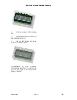
Add the left panel.
( )
Add the right panel and make sure the
hole is aligned with the power connect J1.
( )
Add the bottom panel.


