

DIS. 0534018 COD. 27101448 Istruzione / User’s Manual Pag.2/4
GECA Srl Via E. Fermi 98, 25064 Gussago (Brescia) Italy http://www.gecasrl.it Tel:+39 030/3730218 Fax: +39 030/3730228
Il
GPL
è un gas più pesante dell'aria formato da una mi-
scela composta dal 20-30% di Propano (C
3
H
8
) e dall'80-
70% di Butano (C
4
H
10
). La densità relativa all'aria è 1,56
per il Propano e 2 per il Butano, il LIE è 2,1%v/v per il Pro-
pano e 1,5 %v/v per il Butano. Le tarature per GPL sono
normalmente effettuate con gas Butano.
I sensori devono essere installati come descritto nelle ap-
posite istruzioni ad essi allegate. Dopo l'installazione si de-
ve applicare l'etichetta autoadesiva inserita nella confezio-
ne con il tipo di gas indicato sull'etichetta di collaudo del
sensore remoto.
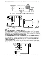
In Fig.3 sono indicate le dimensioni della centralina che
viene montata a parete con tre tasselli.
In Fig.2 è illustrato lo schema di collegamento da rete con
la sirena ed
elettrovalvola normalmente chiusa
.
I morsetti sono di tipo ad innesto polarizzati, si consiglia, di
ancorare i cavi nella custodia per evitare eccessive solleci-
tazioni ai morsetti.
La distanza fra la centrale ed il sensore, non deve essere
superiore a 100 metri utilizzando un cavo 3x1,5 mm2. op-
pure non deve essere superiore a 200 metri utilizzando un
cavo 3x2,5 mm
2
. Non è necessario utilizzare cavi scher-
mati.
La valvola di blocco gas, a riarmo manuale, va installata
all'esterno del locale, in posizione chiaramente segnalata
e protetta dalla pioggia diretta.
Guasti
In caso di guasto del sensore, errato collegamento, inter-
ruzione o cortocircuito dei cavi tra centrale e sensore, si
attiva il relè "FAULT" e la segnalazione ottica a Led giallo
"FAULT".
Quest'ultimo, se richiesto, può essere utilizzato per segna-
lare a distanza un avvenuto guasto o la mancanza di ali-
mentazione alla centralina.
Il relè “FAULT” è normalmente eccitato con contatti in scam-
bio liberi da tensione.
Durante la fase di preriscaldo del sensore, che è di circa
30 secondi, i relè di allarme rimangono inibiti, mentre il Led
giallo e il relè "FAULT" vengono attivati.
Verifiche periodiche
Per verificare il funzionamento della centrale premere il
pulsante "TEST". Si illuminerà la barra Led, si attiverà il
relè "ALARM1", dopo 30 secondi il relè "ALARM2" e il 4°
Led rosso. Per ripristinare le condizioni di funzionamento
normale, premere il pulsante "RESET".
Si consiglia di effettuare la verifica di funzionamento ogni
6-12 mesi.
Avvertenze
ATTENZIONE: il pulsante "TEST" simula un situazio-
ne di allarme e provoca il blocco dell'impianto.
AVVERTENZA IMPORTANTE: La centrale non neces-
sita di regolazioni dopo l'installazione. I trimmer di ta-
ratura sigillati posti sul Circuito Stampato non devo-
no essere manomessi pena la perdita di ogni garanzia
e il pericolo di rendere l'apparecchio non funzionante.
LPG
is a gas heavier than air consisting of a mixture of
20-30% Propane (C
3
H
8
) and 80-70% Butane (C
4
H
10
).
Propane density as to air is 1.56 and its LEL is 1.56%v/v .
Butane density as to air is 2 and its LEL is 2.1%v/v. GPL
remote gas sensors are normally calibrated with Butane.
The remote gas sensor must be installed following instruc-
tions enclosed in its packaging. After installation we advise
to stick the enclosed self-adhesive label that show the
calibrated gas written on the remote sensor test label. Fig.
3 shows the instrument size. It should be wall-mounted by
three screw anchors. Fig. 2 shows the AC powering con-
nection with alarm siren and
normally closed solenoid
valve
.
The terminals are non reversible and plug-in. Therefore
the cables should be anchored to the case in order to
avoid terminal overstress. The distance between the in-
strument and the sensor must not exceed 100 meters us-
ing a 3x1.5 mm
2
cable, or 200 meters using a 3x2.5 mm
2
cable. It is not necessary to use shielded cables.
The valve for the gas cut-off should be installed outside
the room in a clearly indicated position and should be pro-
tected from rain.
Fault
In case of damaged sensor, wrong wiring connection, in-
terruption or cable short circuit between the instrument
and the sensor, both the "FAULT" relay and the optical in-
dication of the yellow LED "FAULT" will deactivate.
The "FAULT" relay, if necessary, can be used both to sig-
nal remotely an occurred damage or to signal the absence
of power to the instrument.
The "FAULT" relay, is normally-activated relays outputs
(tension-free change over contacts).
During the preliminary heating time of the sensor (about
30 seconds), the alarm relays are inhibited, while the yel-
low LEDs and the "FAULT" relay are activated.
Periodical Testing
To check the instrument operation, push the "TEST" but-
ton. The LED bar will illuminate and the "ALARM 1" relay
will activate. After 30 seconds the "ALARM 2" relay and
4th red LED will activate. To reset the normal working
conditions, push the "RESET" button.
Operation testing should be carried out every 6/12 month.
Warnings
CAUTION: the "TEST" button simulates an alarm
condition and causes the blockage of the plant.
VERY IMPORTANT WARNING: The doesn't need ad-
justments after being installed. The sealed calibration
trimmers placed on the Printed Circuit must not be
tampered with under penalty of loosing every guaran-
tee and under the risk and danger to make the in-
strument not operating.