

1905-CP and 1907-CP Thermostatic Valves
Installation Instructions
1
For additional technical assistance, call 800/TEC-TRUE (800-832-8783) or visit our website at chicagofaucets.com.
In order to complete the installation, you will need the following tools and supplies:
• Phillips Screwdriver, #1, #2, #3
• Drill, with 3/16˝ Bit
• Adjustable Wrench
• Mallet
Safety Information
Read this entire user guide to ensure proper installation. Compliance and conformity to local codes and ordinances is the
responsibility of the installer. The following safety notes must always be complied with during handling of this product:
• Make sure there is enough space and lighting available during installation and service.
• Do not modify or convert this Chicago Faucets product yourself. All warranties will be voided.
Notice to the Installer
• Read this entire instruction sheet before installing to ensure proper installation.
• Installation must comply with local codes and ordinances.
• Do not use pipe dope.
• Care shall be exercised when installing the device to prevent marring the exposed, decorative surfaces.
The supply piping to these devices shall be securely anchored to the building structure to prevent installed device from
unnecessary movement when operated by the user.
NOTE: The information in this manual is subject to change without notice.
Installation may be performed at different times of construction by different individuals.
For this reason, these instructions should be left on-site with the facility or maintenance manager.
NOTE: Installation should be in accordance with accepted plumbing practices. Flush all piping thoroughly before installation.
• Tape Measure
• Sealant
• Silicone-based Lubricant
• 1/2˝ Deep Socket or
#3 Flat Head Screwdriver
Valve Construction: Combination mixing valve, with heavy cast bronze body and
brass stem. Concealed adjustable high temperature limit stop. Available with
ADA-compliant ABS or metal lever handle.
Connections: 1/2˝ Sweat Inlet/Outlet
Capacity: 4 gpm @ 45 psi ΔP 50/50 mix
Maximum Hot Water Supply Temperature: 190°F (88°C)
Minimum Hot Water Supply Temperature (Approach
Temperature): 10°F (5.5°C) above set point
Maximum Operating Pressure: 125 psig (862 kPa)
Temperature Ranges (for +/- 3°F performance): ASSE 1016 Type T/P: 90-110°F
(32-43°C)
ASSE 1016 Type T: 80-120°F (27-49°C)
High Temperature Limit Stop: Adjustable (factory set at 110°F [43°C])
Maximum Static Pressure: 125 psig (862kPa)
Minimum Flow: 0.5 gpm (1.89 L/min)
Approval Standards: ASSE 1016 / ASME A112.1016 / CSA B125.16, ASME
A112.18.1 / CSA B125.1
Listing: ASSE 1016 / ASME A112.1016 / CSA B125.16, IAPMO cUPC
Shipping Weight: 3.5 lbs. (1.6 kg)
NOTE: This valve for use with shower heads rated at 1.5 GPM (5.7 L/min) or higher.
All 1905-CP and 1907-CP combination mixing valves meet above performance
specifications based on typical operating conditions as stated in ASSE 1016 (45 psi
pressure differential, hot water supply between 140°-180°F (60°-82°C), cold water
supply less than 70°F (21°C). If your operating conditions vary from those stated in
the standard, performance may vary as well. Consult your local sales representative
or a Chicago Faucet Representative to discuss your specific application. All Chicago
Faucets thermostatic mixing valves perform to the requirements of standards ASSE
1016 / ASME A112.1016 / CSA B125.16 and ASME A112.18.1 / CSA B125.1.
To Install
1. Position mixer 1-15/16˝ ± 1/2˝ [49mm ± 13mm] from inlet center to finished wall surface. The tub outlet port is marked “TUB” and should face down. Facing front of mixer, connect hot water to left
side and connect cold water to right side. The valve has “C” and “H” cast into the body near the appropriate inlet ports.
2. Valve is factory-set for standard inlets. If
reversed inlets
are required due to back-to-back installation (Cold water supply on the left and Hot water supply on the right), follow instructions a – d below:
a. Connect
cold inlet to hot port
(“H”) and
hot inlet
to
cold port
(“C”).
Note:
Do not turn valve upside down. If valve is upside down, water will not flow properly
through tub spout or showerhead.
b. Turn water off with checkstops, remove bonnet and cartridge.
c. Reinstall cartridge. “H” on the cold side of the valve body and “C” should be on the hot side of the valve body.
d. Reinstall bonnet with high temperature limit stop on it.
Note: Be certain that valve opens in full cold!
e. Hot and Cold inlets should be re-identified for reversed inlets to avoid confusion during future maintenance.
3. For
tub and shower installations
(see Figure 1). Pipe bottom outlet port “TUB” directly to the diverter tub spout. The mixer body is designed to operate without the use of a twin ell. Pipe top outlet
port “S” to the showerhead.
4. For
shower only installation
(see Figure 2). Pipe top outlet port “S” directly to the showerhead and plug bottom port.
5. Rough-in guide installation:
a. When piping installation is complete and before doing the finished wall, slide rough-in guide onto the mixer stem and press it into place (see Figure 4).
b. The rough-in guide will insure the proper size opening for mixer and checkstop shut-off and repair accessibility, as well as protect the chrome-plated sleeve from damage during drywall and tile
installation.
6. To install dial gaskets, peel backing off gaskets and attach gaskets to inside of dial plate. Attach indicator plate gasket to the back of the trim plate making sure horizontal holes on the gasket
matches horizontal holes on the trim plate. Indicator plate locator hole matches diagonal hole on the trim plate. Peel off backing of the trim plate gasket and attach to the inside top edge of the trim
plate. Gasket should be approximately 1/16˝ beyond the plate edge.
7. a. Install trim plate.
b. Snap on the indicator plate. Guide on the back of the plate goes into the locator hole.
c. Install sleeve O-ring on the bonnet. Slide sleeve on the bonnet.
CAUTION:
Indicator plate must be installed before sleeve.
d. Install handle and tighten the set screw.
CAUTION:
When soldering during installation process, do not
heat the valve any higher than the temperature required to flow solder. Excessive overheating of the valve may cause damage to the
cartridge mechanism.
By following this recommendation, you will be able to solder the valve without removing either the cartridge or the checkstop internals.
If either brazing or resistance (electric) solder is to be used, all valve internals must be removed.
8. Maximum temperature setting adjustment (see Figure 5) must be set on the job to in no case greater than 110°F (43°C). The high temperature limit stop is located on the bonnet.
Rotate handle to the maximum desired outlet temperature. With an open-end wrench, screw high temperature limit stop into bonnet until it touches stem’s shoulder.
Close valve and open it to full hot to verify settings.
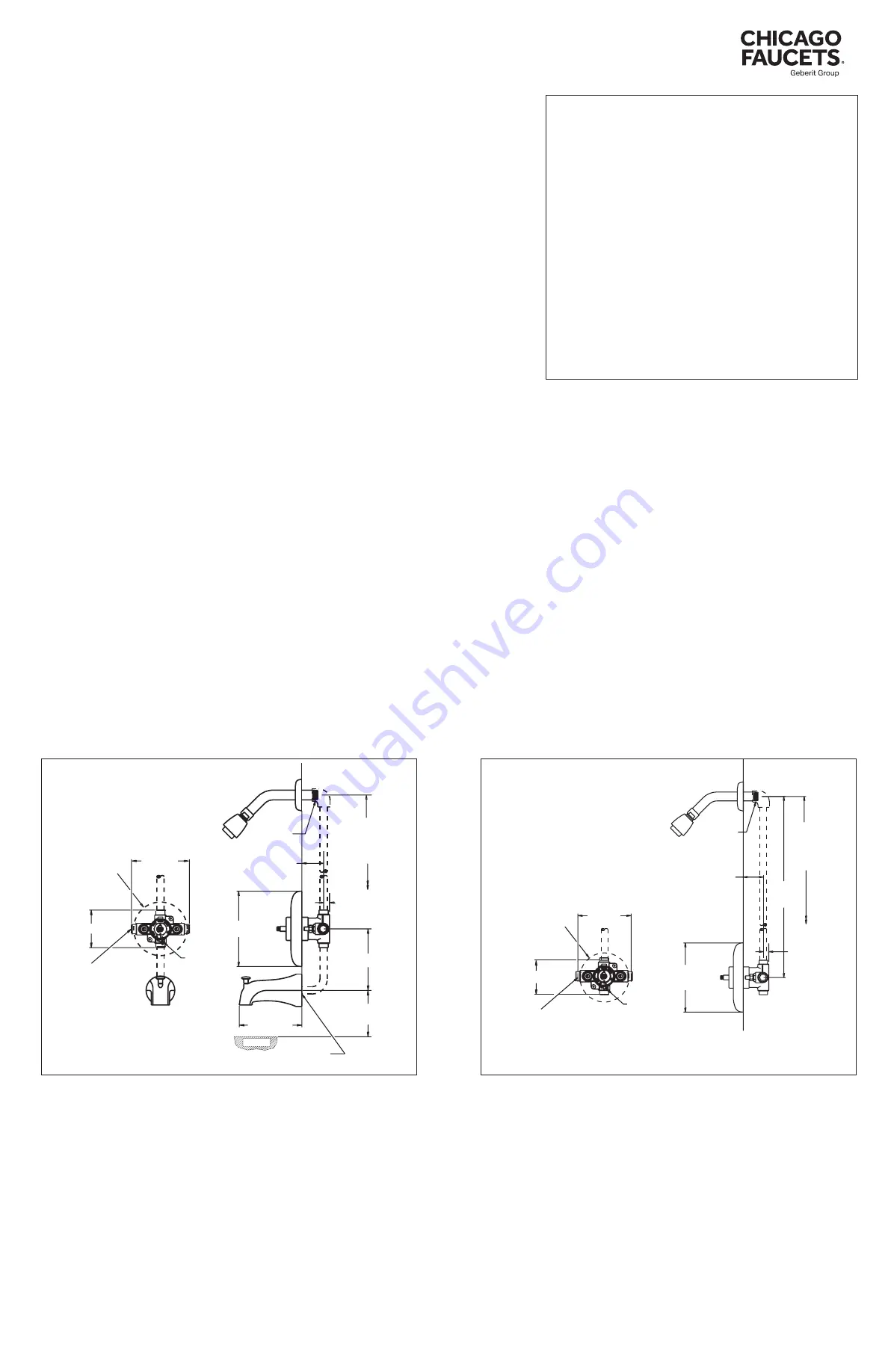
Figure 1: Rough-in Dimensions - Tub & Shower
Figure 2: Rough-in Dimensions - Shower Only
5-3/8" [137]
12" [305]
4" [101]
APPROX.
1-7/16" [37] MIN.
2-7/16" [62] MAX.
8-1/2" [216]
WALL
1/2" [13]
TUB RIM
1/2-14" NPT
MALE INLET
1/2" COPPER
SLIP JOINT
CONNECTION
3-1/4" [82]
5" [127]
4-5/8" [118] DIA
ROUGH-IN
GUIDE
1/2" COPPER SWEAT
CONNECTIONS
NOTE:
'T' TO BE
ON BOTTOM
AS SHOWN
78" [1981]
APPROX.
TO FINISHED
FLOOR
TUB OUTLET
TO BE PLUGGED.
PLUG BY OTHERS.
5" [127]
24" [609]
APPROX.
WALL
1-7/16" [37] MIN.
2-7/16" [62] MAX.
1/2" [13]
1/2" COPPER SWEAT
CONNECTIONS
1/2-14" NPT
MALE INLET
78" [1981]
APPROX.
TO FINISHED
FLOOR
4-5/8" [118] DIA
ROUGH-IN
GUIDE
NOTE:
'T' TO BE
ON BOTTOM
AS SHOWN
3-1/4" [82]
All dotted line piping
supplied by others
All dotted line piping
supplied by others
See specification drawing for all other dimensions.