background image

16

1. 

To enter diagnostics, press and hold the

SELECT

button until (000 – –) shows in 

the display.

A

The first 3 digits indicate water meter
operation as follows:

000 (steady) = soft water not in 
use…no flow through the meter.

—OPEN A NEARBY SOFT WATER FAUCET—

000 to 199 (continual) = repeats display for each 
gallon of water passing through the meter.

If you don’t get a reading in the display, with faucet 
open, pull the sensor from the valve outlet port. Pass 
a small magnet back and forth in front of the sensor. 
You should get a reading in the display. If you get a 
reading, shut off water supply, unhook the in and out 
plumbing and check the turbine for binding.

B

The letter (P) and dash(es) indicate 

POSITION

switch 

operation. The letter appearing means the switch is 
closed; the dash means the switch is open. Use the 

TOUCH OR HOLD (RECHARGE TONIGHT–RECHARGE NOW) 

button to manually advance the valve into each cycle  
and check correct switch operation.

C

While in this diagnostic screen, the following information
is available and may be beneficial for various reasons.
This information is retained by the computer from the
first time electrical power is applied to the control.

Press and hold the 

UP

button to display the number 

of days this control has had electrical power applied.

Press and hold the 

DOWN

button to display the

number of regenerations initiated by this control 
since the SR code number was entered.

2.

Press the 

SELECT

button and hold in

three seconds until a Service Rating code
appears in the display.

For correct water softening system 
operation, the model code must be F35 for model GNSF35Z.

To reset the code,

press the 

UP

or 

DOWN

button until the 

correct number shows.

3. 

Press the 

SELECT

button to return to the present time

display. 

If the code was changed, make ALL the timer settings.

NOTE: 

If the control is left in a diagnostic display or a 

flashing display when setting times or hardness, present time
automatically returns if a button is not pressed within four
minutes.

About the water softener system.

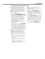
CORRECT SWITCH

DISPLAYS

VALVE CYCLE STATUS

— —

Valve in service, fill, brining, backwash
or fast rinse position.

— P

Valve rotating from one position to another

Turbine Switches

Water
Meter (A)

Switch (B)

OR

Service: Manually Initiated Electronic Diagnostics

Motor

Turbine

Turbine support
and shaft

Sensor
housing

Position
switch

Valve
outlet

Summary of Contents for GNSF35Z

Page 1: ...ep by Step Instructions 6 11 Tools and Materials Required 4 Unpacking and Inspection 3 Operating Instructions Tips Breaking a Salt Bridge 13 Cleaning Nozzle and Venturi Assembly 13 Features 14 Service 12 Water Softener System 12 17 Care and Cleaning 18 Troubleshooting Tips 19 21 Consumer Support Consumer Support Back Cover Parts List Catalog 22 25 Product Registration 29 30 Warranty 31 Owner s Man...

Page 2: ...atures below freezing or exposed to any type of weather Water freezing in the system will break it Do not attempt to treat water over 100 F Do not install in direct sunlight Excessive sun heat may cause distortion or other damage to non metallic parts Properly ground to conform with all governing codes and ordinances Use only lead free solder and flux for all sweat solder connections as required b...

Page 3: ...side down drop drag or set on sharp protrusions Maximum allowable inlet water pressure is 125 psi If daytime pressure is over 80 psi nighttime pressure may exceed the maximum Use a pressure reducing valve if necessary Adding a pressure reducing valve may reduce the flow The softener works on 24 volt 60 Hz electrical power only Be sure to use the included transformer Be sure the electric outlet and...

Page 4: ...n and out fittings included with the softener are 3 4 nominal copper sweat tubes You should maintain the same or larger pipe size as the water supply pipe up to the water softener inlet and outlet Use the included bypass valve to install the softener The bypass valve allows you to turn off water to the softener for servicing but still have water in the house pipes The in and out fittings referred ...

Page 5: ...olt outlet MAIN WATER PIPE Soft water Hard water Copper tube 3 4 2 Washer 2 Installation adapter 2 see above INLET NOTE Threads on the installation adapters are 1 male pipe If 1 pipes are needed do not use the copper tubes and nuts included Buy 1 pipe thread female adapter and plumb directly to 1 threads on installation adapters 24V transformer 120 volt outlet Bypass valve Hard water to outside fa...

Page 6: ...ed to attach to the valve drain fitting Fig 4A To keep water pressure from blowing the hose off use a hose clamp to secure in place Locate the other end of the hose at a suitable drain point floor drain sump laundry tub etc that terminates at the sewer Check and comply with local codes IMPORTANT If more drain hose is needed it should be ordered from GE Parts at 800 626 2002 The water softener will...

Page 7: ... Place bypass valve in bypass position by pushing the stem inward 7 6 5 4a Fig 4B Fig 5 Overflow drain hose Hose clamp Grommet Clip 1 4 NPT threads Barbs 1 2 O D copper tube not furnished Cut barbs from drain fitting Compression fitting 1 4 NPT X 1 2 O D tube not furnished Do not connect to valve drain hose Fully open the house main water pipe shutoff valve Observe a steady flow from both faucets ...

Page 8: ...es the hardness value UP increases the hardness value NOTE Each press of a button changes the display by 1 between 1 and 25 Above 25 the display changes 5 at a time 25 30 35 etc Holding a button in changes the numbers at a rapid rate 3 When the display shows your water hardness in grains per gallon press SELECT to accept NOTE If there is clear water iron in your water supply you will need to incre...

Page 9: ...difference between these two cycles is highly dependent on the water usage and hardness at a particular installation NOTE California Regulations require this feature to be ON for installations in California To access the Salt Efficiency press and hold the SELECT button for 3 seconds The System Diagnostics display will appear Press the SELECT button again and the Salt Efficiency display will appear...

Page 10: ...contaminate your water supply and will not cause bacteria to form or grow However during shipping storage installing and operating bacteria could get into the softener For this reason sanitizing as follows is suggested when installing NOTE Sanitizing is recommended by the Water Quality Association for disinfecting Be sure to complete all installation steps including timer programming Remove the br...

Page 11: ... iron removal Refer to Cleaning Iron Out of the Water Softening System section Canada working pressure limits 1 4 7 0 kg cm2 GNSF35Z Rated capacity see rating label on water softener Rated efficiency see rating label on water softener Amount of high capacity resin lbs cu ft 48 9 94 Resin tank nominal size in dia x height 9 x 40 Service flow rate gpm see rating label on water softener Water supply ...

Page 12: ...n beads To make the brine water flows into the salt storage area during the fill stage as shown Brining During brining brine travels from the salt storage area into the resin tank Brine is the cleaning agent needed to remove hard minerals from the resin beads The hard minerals and brine are discharged to the drain The nozzle and venturi create a suction to move the brine maintaining a very slow ra...

Page 13: ...tighten the cap or housing IMPORTANT Be sure small holes in the gasket are centered directly over the small holes in the nozzle and venturi housing Install with numbered side up concave side down Cap O ring seal Screen support Screen Screen Nozzle Venturi Nozzle Venturi housing Gasket Fill Flow plug Breaking a Salt Bridge Sometimes a hard crust or salt bridge forms in the salt storage area It is u...

Page 14: ...immediate recharge and when over in about two hours you will have a new supply of soft water Once started you cannot cancel this recharge Feature Optional Recharge Controls Feature Memory If electrical power to the water softening system is interrupted the control display is blank and the blue indicator light is off but the control keeps correct time for about 6 hours When power is restored you ha...

Page 15: ...agnostics NO POWER POWER OK REPAIR AS NEEDED CONTROL DEFECTIVE Do manual diagnostics to verify proper function Electrical power was off Reset the correct time of day Investigate reason for power loss www GEAppliances com Service Electronic Demand Time Features and Service If you are not getting soft water and an error code is not displayed use the procedures below to find the problem First make th...

Page 16: ... retained by the computer from the first time electrical power is applied to the control Press and hold the UP button to display the number of days this control has had electrical power applied Press and hold the DOWN button to display the number of regenerations initiated by this control since the SR code number was entered 2 Press the SELECT button and hold in three seconds until a Service Ratin...

Page 17: ...the liquid level over an extended period of time NOTE Be sure a salt bridge is not preventing water from contacting salt See Care and cleaning of the water softening system section If the water softening system does not draw brine check nozzle and or venturi dirty or defective nozzle and venturi not seated properly on gasket restricted drain check drain fitting and hose defective nozzle and ventur...

Page 18: ...em takes hardness minerals calcium and magnesium out of the water Also it can control some see Specification Guidelines section clear water iron With clear water iron water from a faucet is clear when first put into a glass After 15 to 30 minutes the water begins to cloud or turn rust colored A water softening system will not remove any iron that makes the water cloudy or rusty as it comes from th...

Page 19: ...to electrical display and read Program Memory section outlet Electrical outlet on a circuit that NOTE The electrical outlet for the softener should be continuously can be switched off live so it cannot be accidentally switched off Manual bypass valve in bypass Be sure the bypass valve stem is positioned properly with the position knob in the OUT position Observe instructions on the decal at the en...

Page 20: ... color Acidic water in copper plumbing Have the water tested at once after water softening system was installed Water softening system Meter turbine stuck See the Service Manually Inititated Electronic Diagnostics not regenerating section for troubleshooting procedures page 16 Call for service Sensor wire corroded See the Service Manually Inititated Electronic Diagnostics section for troubleshooti...

Page 21: ... has air bubbles Air in system after installation Will go away after it runs for a while and is cloudy Error Code on control Wiring may have worked loose Unplug transformer in control Remove control cover release clips on side Check for loose incorrect wiring connections to electronic board or switch Reconnect as required Reassemble control cover Plug in transformer Wait six minutes for error code...

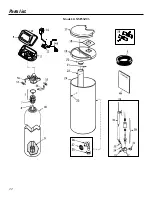
Page 22: ...22 Parts list Model GNSF35Z03 ...

Page 23: ...23 Parts list www GEAppliances com ...

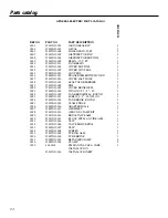
Page 24: ... 1 0019 WS33X10002 RIM 1 0020 WS31X10003 COVER BRINEWELL 1 0021 WS02X10009 WING NUT 1 4 20 1 0022 WS32X10002 TANK BRINEWELL ROUND 1 0023 WS02X10011 SCREW 1 4 20 NYLON 1 0024 WS32X10003 TANK BRINE ROUND 1 0025 WS18X10003 CLAMP HOSE 1 0026 WS22X10016 ADAPTER HOSE 1 0027 WS22X10017 GROMMET 1 0028 WS35X10035 GROUND CLAMP KIT 1 0029 WS15X10005 BRINE VALVE ASM 1 0030 WS35X10003 FLOAT STEM GUIDE ASM 1 00...

Page 25: ...T 1 0115 WS03X10015 CONE SCREEN 1 0116 WS22X10021 PLUG FILL FLOW 3 GPM 1 0117 WS03X10017 NUT FERRULE 1 0118 WS15X10009 NOZZLE VENTURI ASM 1 0119 WS03X10018 RETAINER 1 0120 WS03X10019 SEAL O RING 1 4 X 3 8 2 0121 WS15X10010 BODY VALVE 1 0122 WS03X10020 SPRING 1 0123 WS22X10022 PLUG DRAIN SALT 1 0130 WS35X10005 SEAL KIT 1 0132 WS22X10023 ADAPTER DRAIN HOSE 1 0133 WS03X10021 O RING 5 8 X 13 16 1 0134...

Page 26: ...26 Notes ...

Page 27: ...27 Notes ...

Page 28: ...28 Notes ...

Page 29: ... protection or you may request your money back on the remaining value of your contract No questions asked It s that simple Protect your refrigerator dishwasher washer and dryer range TV VCR and much more any brand Plus there s no extra charge for emergency service and low monthly financing is available Even icemaker coverage and food spoilage protection is offered You can rest easy knowing that al...

Page 30: ...the peace of mind of knowing we can contact you in the unlikely event of a safety modification After mailing the registration below store this document in a safe place It contains information you will need should you require service Our service number is 800 GE CARES 800 432 2737 Read your Owner s Manual carefully It will help you operate your new appliance properly Model Number Serial Number E ma...

Page 31: ...ters membranes or batteries Replacement of house fuses or resetting of circuit breakers Damage to the product caused by accident fire floods or acts of God Incidental or consequential damage caused by possible defects with this appliance Damage caused after delivery This warranty is extended to the original purchaser and any succeeding owner for products purchased for home use within the USA In Al...

Page 32: ...extended warranty and learn about special discounts that are available while your warranty is still in effect You can purchase it on line anytime or call 800 626 2224 during normal business hours GE Consumer Home Services will still be there after your warranty expires Parts and Accessories www GEAppliances com Individuals qualified to service their own appliances can have parts or accessories sen...

Reviews: