

3
/1 parameter. (Action only valid when parameter H2 = 3)
maximum limit (Not Applicable).
‘lP’ Low pressure alarm
Special Functions:
Controller 1: suction pressure lower than the minimum
limit
The Special Functions can be activated by:
Controller 2: condensing pressure lower than the
minimum limit
‘d1’ Discharge temperature alarm
Digital scroll only: Discharge end temperature is too high
‘EP’ Error pressure
Controller 1: suction pressure sensor failure
Controller 2: condensing pressure sensor failure (N/A)
‘Fr’ Fast recovery alarm
Controller 1: fast recovery from low suction pressure
Controller 2: fast recovery from low condensing pressure
(N/A)
‘hr' High discharge pressure alarm
Controller 1: high discharge pressure recovery
Controller 2: high discharge pressure recovery (N/A)
‘
rE’ Emergency run
Controller 1: runs with c6 numbers of compressors
Controller 2: runs with c6 numbers of fans (N/A)
‘E1’ Feedback alarm 1
Controller 1: digital input associated with compressor 1
has changed into alarm state (safety chain)
Controller 2: digital input associated with fan(s) has
changed into alarm state (safety chain) (N/A)
‘E2’ Feedback alarm 2
Controller 1: digital input associated with compressor 2
has changed into alarm state (safety chain) (N/A)
‘n1’ Service alarm 1
Controller 1: compressor 1 operating time higher than
run limit (A9)
Controller 2: fan operating time higher than run limit (A9)
(N/A)
‘n2’ Service alarm 2
Controller 1: compressor 2 operating time higher than
run limit (A9)
Er Data error
Data send to the display is out of range
Messages
‘---‘ No data to display
The display will show an “---” at node start up and when
no data is send to the display.
‘In’ Reset to default values activated
The display will show an “In” when the factory default
configuration data set
is initialized.
‘Id’ Wink request received
The display will show a flashing “Id” when the wink
request was received. The flashing “Id” will be shown on
the display until the service button will be pressed, or a
30 min delay timer will expire or a second wink request
is received. This function is action only when using
SNMP protocol. The node is offline and no application is
running. This is the result of a network management
command and will happen for example during node
installation.
WARNING: Do not set the controller outside of the
application limits as shown in section 4.
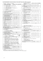
For a full description of controller settings please refer to
the table on page 8.
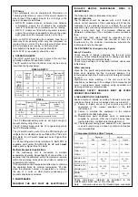
g) Anti-Cycle & Delay Start Timer – Standard on
NSQ/NCQ, optional on NSE NCE, with electrical options
W & T.
Anti-Cycle Function
Units are fitted with a compressor Anti-Cycle and Delay
Start timer. This timer will prevent rapid repeated
starting of the compressor, by enforcing a maximum of
10 compressor starts per hour. The timer runs from Start
to Start, therefore if the compressor has run for more
than 6 minutes it will be allowed to start again
1. Press
and
together for more than 5
seconds. A flashing 0 is displayed.
2. Press
or
until the password is displayed
(default = 12). If password was changed, select the new
password.
3. Press
to confirm password , A 0 is displayed and
the Special Function mode is activated.
4. Press
or
to select the function. The number
of special functions is dynamic and controller
dependent. See list below.
5. Press
to activate the function without leaving the
special function mode.
6. Press
to activate the function and leave the
special function mode.
Most of the Special Functions work in a toggle mode,
the first call activates the function, and the
second call
deactivates the function.
The indication of the function can only be
displayed after exiting the special function mode.
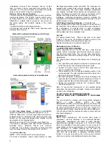
• 0: Display test function
• 1: Displays the current TCP/IP address
• 2: Set the controller TCP/IP address to the default
value: 192.168.1.101
• 3: Resets all parameters to the factory default setting.
The controller will indicate “oF” during the reset.
The data to be shown on the display can be selected by
the user. In case of an alarm, the alarm code is
displayed alternately with the selected data. The user
can inhibit the alarm code. Press the
button to scroll
through all possible displayable data.
The display will show for one second the numerical
identifier of the data and then the selected data. After
two minutes the display will return to the by parameter /1
selected data.
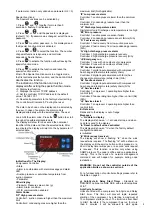
Indications On The Display:
Compressor Controller
• State
• Alarm in combination with alarm message and alarm
LED
• Suction pressure or saturation temperature from
suction pressure
• Parameter
Other display
• Pressure: Pressure value in bar (g)
• Alarm: Alarm condition
• IR: IR communication enabled
Alarm Codes
‘HP’ High pressure alarm
Controller 1: suction pressure higher than the maximum
limit
Controller 2: condensing pressure higher than the
Summary of Contents for Searle NSQ Series
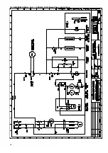
Page 10: ...11a SCQ All Units 1MX A SCQ 611 06 XXX W Single Phase with AC Fans 10...
Page 11: ...11b SCQ All Units 3MX A SCQ 613 06 XXX W Three Phase with AC Fans 11...
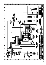
Page 14: ...11e NSQ NSE15 1MX A 44 611 16 XXX W ZB15 Single Phase with AC Fans 14...
Page 16: ...11g NSQ NSE19 to 26 1MX A B or C 44 611 06 XXX W ZB19 to ZB26 Single Phase AC Fans 16...
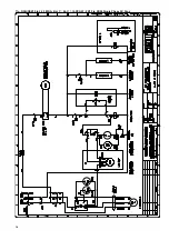
Page 18: ...11i NSQ NSE15 to 45 3MX A B C 44 613 06 XXX W ZB15 to ZB45 Three Phase AC Fans 18...
Page 20: ...11k NDQ 30 to 45 3MX S C 44 613 XDX W ZBD30 to ZBD45 Three Phase AC Fans 20...
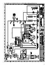
Page 21: ...11l NCQ NCE 56 to 110 3MX S D E 2 3 44 633 16 XXX W ZB56 to ZB11 Three Phase AC Fans 21...
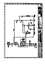
Page 22: ...11m NSQ NSE 15 to 30 1MX S A B C 2 3 44 611 ST2 Layout Diagram 22...
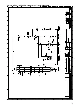
Page 23: ...11n NSQ NSE 09 to 18 3LX S 15 to 45 3MX S A B C 2 3 44 613 ST2 Layout Diagram 23...
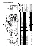
Page 24: ...11o NCQ NCE 24 to 48 3LX S 56 to 110 3MX S D E 2 3 44 633 3 ST2 Layout Diagram 24...
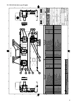
Page 25: ...12 DIMENSIONS Case A B C 25...


