background image

20

  D
 GB
  F
  E

96180-09.2013-DGbFEI

5

|

 Electrical connection   

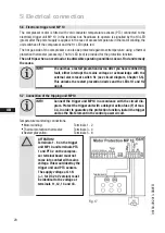
ATTENTION! 
Terminals 1 - 6 on the trigger 
unit MP 10 and terminals PTC 
1 and PTC 2 on the compres-
sor terminal board must not 
come into contact with mains 
voltage. This would destroy the 
trigger unit and PTC sensors.
The supply voltage at L1-N 
(+/- for DC 24 V version) must 
be identical to the voltage at 

terminals 11, 12, 14 and 43. 

5.6  Electronic trigger unit MP 10

The  compressor  motor  is  fitted  with  cold  conductor  temperature  sensors  (PTC)  connected  to  the 
electronic trigger unit MP 10 in the terminal box. Readiness to operate is signalled by the H3 LED 
(green) after the power supply is applied. In the case of excess temperature in the motor winding, the 
unit switches off the compressor and the H1 LED lights red.
The hot gas side of the compressor can also be protected against overtemperature using a thermal 
protection thermostat (accessory). The H2 LED (red) is provided for the protection function.

The unit trips when an overload or inadmissible operating conditions occur. Find and remedy 
the cause.

5.7  Connection of the tripping unit MP10

INFO! 

 Connect the trigger unit MP10 in accordance with the circuit dia-
gram. Protect the trigger unit with a delayed-action fuse (F) of max. 

4 A. In order to guarantee the protection function, install the trigger 
unit as the first element in the control power circuit.

Temperature monitoring connections:

 Motor winding: 


Terminals 1 - 2

 Thermal protection thermostat: 

Terminals 3 - 4

 Restart prevention:   


Terminals 5 - 6

INFO! 


The unit has a restart prevention device. After you have rectified the 
fault,  either  interrupt  the  mains  voltage  or  acknowledge  with  the 
external  alarm  reset  switch  S1  (see  circuit  diagram,  Chapter  5.5). 
This unlocks the restart prevention device and the LEDs H1 and H2 

go out.

Fig. 17

Terminal board 

Summary of Contents for HGX5/725-4 R134a

Page 1: ...96180 09 2013 DGbFEI engineering for a better world GEA Refrigeration Technologies Bock Compressor HGX5 R134a Assembly instructions HGX5 725 4 R134a HGX5 830 4 R134a HGX5 945 4 R134a 1 2 3 4 5 6 7 8 9 10 11 12 13 ...

Page 2: ... the compressor can result in serious or fatal injury Observe the safety instructions contained in these instructions These instructions must be passed onto the end customer along with the unit in which the compres sor is installed GEA Bock GmbH 72636 Frickenhausen GEA Bock GmbH Benzstraße 7 72636 Frickenhausen Germany Telephone 49 7022 9454 0 Fax 49 7022 9454 137 bock gea com www bock de Manufact...

Page 3: ...n for direct or part winding start 5 3 Basic circuit diagram for part winding start with standard motor 5 4 Special motor design for direct or star delta start 5 5 Basic circuit diagram for star delta start with special motor 5 6 Electronic trigger unit MP 10 5 7 Connecting the trigger unit MP 10 5 8 Functional test of the trigger unit MP 10 5 9 Oil sump heater accessories 6 Commissioning 23 6 1 P...

Page 4: ...tential dangers WARNING Refrigerating compressors are pressurised machines and therefore require particular caution and care in handling Risk of burns Depending on the operating conditions surface temperatures of over 60 C on the pressure side or below 0 C on the suction side can be reached The maximum permissible overpressure must not be exceeded even for testing purposes 1 1 Identification of sa...

Page 5: ...refrigerating compressor named in the title is intended for installing in a machine within the EU according to the EU Directives 2006 42 EC Machinery Directive 97 23 EC Pressure Equipment Directive and 2006 95 EC Low Voltage Directive Commissioning is only permissible if the compressor has been installed in accordance with these assembly instructions and the entire system into which it is integrat...

Page 6: ...drive motor on the compressor case Application range normal refrigerating and air conditioning with R134a Fig 1 2 1 Short description Dimension and connection values can be found in Chapter 9 Name plate Valve plate Cylinder cover Terminal box Transport eyelet Discharge shut off valve Oil pump Suction shut off valve Oil sight glass Drive section Motor section ...

Page 7: ... 2 Machine number 7 Nominal rotation speed 3 maximum operating current 8 Displacement 4 Starting current rotor blocked 9 Voltage circuit frequency Y Part winding 1 10 Nominal rotation speed YY Part windings 1 and 2 11 Displacement 5 ND LP max admissible operating 12 Oil type filled at the factory pressure g Low pressure side 13 Terminal box protection type HD HP max admissible operating Electrical...

Page 8: ...e only oils with high thermal stability Avoid continuous operation near the threshold For operation with capacity regulator The suction gas superheat temperature may need to be reduced or set individually when operating near to the threshold For operation with frequency converter The maximum current and power consumption must not be exceeded In the case of operation above the mains frequency the a...

Page 9: ...st Unlimited application range Supplementary cooling or reduced suction gas temperature R134a Fig 4 Evaporation temperature C Condensing temperature C Suction gas superheat K Suction gas temperature C Max permissible operating pressure LP HP 1 19 28 bar 1 LP Low pressure HP High pressure ...

Page 10: ... inch dimensions can be used The connection diameters of the shut off valves are rated for maximum compressor output The actual required pipe cross section must be matched to the output The same applies for non return valves Fig 9 graduated internal diameter F E D C B 1 2 3 K Alternativbezug Baumustergeprüft Lieferantenzeichnung K Auftrag PL Entwicklungsstand 120 400 0 5 Bearb Datum Änderungs Nr W...

Page 11: ...ipes and system components must be clean and dry inside and free of scale swarf and layers of rust and phosphate Only use air tight parts Lay pipes correctly Suitable vibration compensators must be provided to prevent pipes being cracked and broken by severe vibrations Ensure a proper oil return Keep pressure losses to an absolute minimum A rule of thumb Always lay the first pipe section starting ...

Page 12: ...Spindle turn to the left counter clockwise as far as it will go Shut off valve completely opened service connection closed The connection which cannot be shut off is intended for safety devices Fig 14 Opening the service connection Spindle Turn 1 turn clockwise Service connection opened shut off valve opened The connection which cannot be shut off is intended for safety devices Service connec tion...

Page 13: ...ded into two parts Partial winding 1 66 and part winding 2 33 This winding division reduces the start up current needed for a part winding start to approx 65 of that for a direct start INFO A mechanical unloaded start with bypass solenoid valve is not required 5 1 Information for contactor and motor contactor selection All protection equipment switching and monitoring devices must comply with the ...

Page 14: ...1 1W1 PE M Y YY M1 R1 2U1 2V1 2W1 I 33 F1 2 K2 1 2 4 3 4 5 5 6 6 X1 L1 L1 N N 43 43 11 12 14 L S M X2 1 2 3 4 5 6 7 F1 1 F1 2 8 R2 4A F2 S1 9 10 MP10 11 R1 Cold conductor PTC sensor motor winding R2 Thermal protection thermostat PTC sensor F1 1 1 2 2 motor protection switches 66 33 of I A total F2 Control power circuit fuse F3 High pressure safety monitor F4 Safety chain high low pressure monitori...

Page 15: ... 13 N P l 14 L 15 M 16 S P F3 17 18 19 K1 P F4 20 K1 K1T K2 21 22 K1T P B1 23 24 K1 25 E1 26 L1 1 L2 1 L3 1 L1 2 N PE Q1 Main switch M1 Compressor motor K1 Mains contactor part winding 1 K2 Mains contactor part winding 2 K1T Delay relay max 1s S1 Control voltage switch E1 Oil sump heater ...

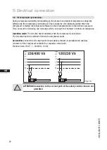
Page 16: ...sely affect the service life of the motor The motor is wired for direct start YY at the factory For part winding start Y YY the bridges must be removed and the motor feed line connected according to the circuit diagram 400 V Direktstart YY Teilwicklungsstart Y YY 1V1 1W1 1U1 2W1 2V1 2U1 L3 L2 L1 L3 L2 L1 L3 L2 L1 1V1 1W1 1U1 2W1 2V1 2U1 400 V Direct start YY Part winding start Y YY 400 V Direktsta...

Page 17: ...Zubehör erforderlich Bezeichnung auf dem Typschild Aufkleber auf Klemmenkasten Y Stern Dreieck Anlauf ist nur im Spannungsbereich 230 V möglich Beispiel 230 V Direktstart Stern Dreieck Start L3 L1 V1 W1 U1 V2 U2 W2 L1 L2 L3 L2 V1 W1 U1 V2 U2 W2 L3 L2 L1 400 V Y nur Direktstart V1 W1 U1 V2 U2 W2 L1 L2 L3 5 4 Sondermotor Ausführung für Direkt oder Stern Dreieck Anlauf Für den Stern Dreieck Anlauf is...

Page 18: ...V1 W1 M 3 M1 Y K3 1 2 3 4 R1 5 6 W2 U2 V2 D K2 1 2 4 3 4 5 5 6 6 X1 L1 L1 N N 43 43 11 12 14 L S M X2 1 2 3 4 5 6 7 F1 1 F1 2 8 R2 4A F2 S1 9 10 MP10 11 Compressor terminal box R1 Cold conductor PTC sensor motor winding R2 Thermal protection thermostat PTC sensor F1 1 1 2 2 motor protection switches F2 Control power circuit fuse F3 High pressure safety monitor F4 Safety chain high low pressure mon...

Page 19: ...S K1 K1 K3 P F3 K4T K3 K2 17 K4T K2 K3 18 19 K4T P F4 20 K5T AL 21 22 K5T P B1 23 24 K1 25 E1 26 L1 1 L2 1 L3 1 L1 2 N PE M1 Compressor motor K1 Mains contactor K2 contactor K3 Y contactor K4T Delay relay S D changeover K5T Delay relay start unloader S1 Control voltage switch AL Start unloader E1 Oil sump heater ...

Page 20: ...sor can also be protected against overtemperature using a thermal protection thermostat accessory The H2 LED red is provided for the protection function The unit trips when an overload or inadmissible operating conditions occur Find and remedy the cause 5 7 Connection of the tripping unit MP10 INFO Connect the trigger unit MP10 in accordance with the circuit dia gram Protect the trigger unit with ...

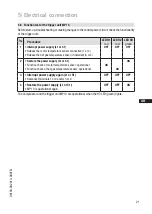
Page 21: ...onnection 1 or 2 Release the hot gas temperature sensor if installed 3 or 4 2 Restore the power supply L1 or S1 ON Function check of motor temperature sensor operational ON Function check of hot gas temperature sensor operational ON 3 Interrupt power supply again L1 or S1 OFF OFF OFF Reconnect terminals 1 or 2 and or 3 or 4 4 Restore the power supply L1 or S1 OFF OFF ON MP 10 is operational again ...

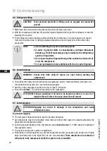
Page 22: ...the compressor is started the refrigerant contained in the oil evaporates due to the decline in pressure This can result in oil foaming and oil exodus which can result in oil hammer in certain circumstances Operation mode The oil sump heater operates when the compressor is shut down The oil sump heater is switched off when the compressor starts Connection Connect the oil sump heater via an auxilia...

Page 23: ...ation side The compressor has undergone trials in the factory and all functions have been tested There are therefore no special running in instructions Check the compressor for transport damage 6 2 Pressure strength test DANGER Bursting The compressor must only be pressurised using nitrogen N2 Never pressurise with oxygen or other gases The maximum permissible overpressure of the compressor must n...

Page 24: ...pen before starting the compressor Check that the safety and protection devices pressure switch motor protection electrical con tact protection measures etc are functioning properly Switch on the compressor and let it run for at least 10 minutes Check the oil level The oil must be visible in the sight glass ATTENTION If larger quantities of oil have to be topped up there is a risk of oil impact ef...

Page 25: ... operating hours Dispose of used oil according to the regulations observe national regulations Annual checks Oil level leak tightness running noises pressures temperatures function of auxiliary devices such as oil sump heater pressure switch WARNING Before starting any work on the compressor Switch off the compressor and secure it to prevent a restart Relieve compressor of system pressure Prevent ...

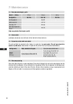
Page 26: ...bricants table The oil type filled as standard in the factory is marked on the name plate This oil type should be used as a preference Alternatives are stated in the extract from our lubricants table below Available accessories can be found on the Internet at www bock de 7 4 Accessories 7 6 Decommissioning Close the shut off valves on the compressor Drain the refrigerant it must not be discharged ...

Page 27: ... 54 2 1 8 72 69 68 1 2 3 2 4 380 420 V Y YY 3 50 Hz PW 440 480 V Y YY 3 60 Hz PW PW Part Winding Winding ratio 66 33 L M H 5 Tolerance 10 relative to the mean value of the voltage range Other voltages and types of current on request Take account of the max operating current max power consumption for design of fuses supply lines and safety devices Fuse Consumption category AC3 All specifications ar...

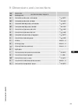
Page 28: ... 830 4 S N Anschluß Leistungsregler Connection capacity co L Brazing connecti O Anschluß L Lötanschluß Ölspiegelregulator Connection oil level reg P Anschluß Öl Differenzdrucksensor Connection oil pressure ÖV Anschluß Ölserviceventil Connection oil service v Q Anschluß Öltemperatursensor Connection oil tempera Anschlüsse Connections SV Saugabsperrventil Rohr L Suction line valve tube DV Druckabspe...

Page 29: ...onnectoin oil pressure switch OIL 7 16 UNF D Connection oil pressure switch LP 7 16 UNF D1 Connection oil return from oil separator 1 4 NPTF E Connection oil pressure gauge 7 16 UNF F Oil drain M22 x 1 5 H Oil charge plug M22 x 1 5 J1 Oil sump heater accessories M22 x 1 5 K Sight glass L Connection thermal protection thermostat 1 8 NPTF O Connection oil level regulator 3 x M6 ÖV Connection oil ser...

Page 30: ...ssor HGX5 R134a complies with the basic require ments of Appendix II 1B of the Machinery Directive 2006 42 EC Applied harmonised standard EN 12693 2008 and the corresponding standards referenced A partly completed machine may only be put into operation when it has been established that the machine into which the partly completed machine is to be installed conforms to the regulations of the Machine...

Page 31: ...r specialist wholesaler and or our representative The Bock service team can be contacted by phone with a toll free hotline 00 800 800 000 88 or via e mail bock gea com Yours faithfully GEA Bock GmbH Benzstraße 7 72636 Frickenhausen Germany We also provide information on the Internet at www bock de For example under the Documentation link you will find Technical information Product information Prod...

Page 32: ...54 0 Fax 49 7022 9454 137 bock gea com www bock de We live our values Excellence Passion Integrity Responsibility GEA versity GEA Group is a global engineering company with multi billion euro sales and operations in more than 50 countries Founded in 1881 the company is one of the largest providers of innovative equipment and process technology GEA Group is listed in the STOXX Europe 600 index ...

Reviews: