


D
GB
F
E
17
96032-04.2015-DGbF
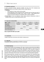
In the factory, the motor is switched for direct starting (YY). For part winding start (Y/YY), remove the
bridges and connect the motor feed cable according to the circuit diagram:
400 V
Direct start YY
Part winding start Y/YY
L1
L2
L3
L1
L2
L3
L1
L3
L2
PTC
PW
II
PW
I
PTC
ATTENTION Property damage possible.
Failure to comply results in reversed fields of rotation and can
cause motor damage. After the motor has started up with part win-
ding 1, part winding 2 must be switched on after max. 1 second
delay. Failure to comply can be detrimental to the service life of
the motor.
Ensure that power is supplied via K1 to winding 1 (70%) (1U1 /
1V1 / 1W1) and via K2 to winding 2 (30%) (2U1 / 2V1 / 2W1). The
motor contactors (K1/K2) are each to be rated for approx. 70% of
the max. operating current.
5
|
Electrical connection


