background image

GE H

EALTHCARE

 PROPRIETARY 

TO 

GE

D

IRECTION

 5344303-100, R

EVISION

 3 

VIVID P3 S

ERVICE

 M

ANUAL

Chapter 8 Replacement Procedures

8-37

6) Remove the LH-side EMI cover and remove two screws from LH-side bottom of the top assembly of 
the system. Refer 

Figure 8-31 on page 8-37 

Figure 8-31   Removing screw top assembly

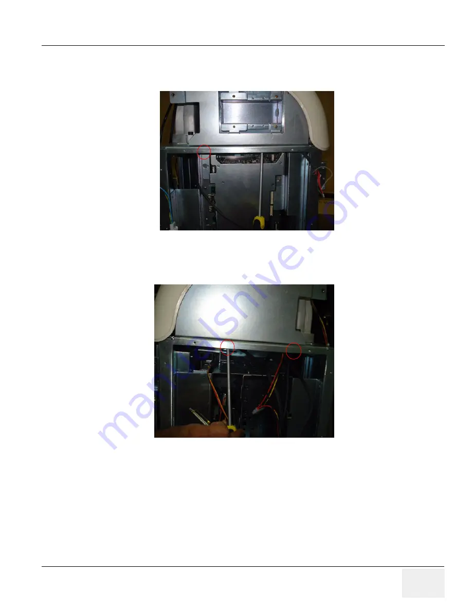
7) Remove RH-side EMI cover and remove two screws from RH-side bottom of the top assembly of the 
system. Refer 

Figure 8-32 on page 8-37 

Figure 8-32   Removing screw top assembly

Summary of Contents for Vivid P3

Page 1: ...Technical Publication Direction 5344303 100 Revision 3 GE Healthcare Vivid P3 Service Manual Copyright 2009 2011 by General Electric Company Inc All Rights Reserved GE Healthcare...

Page 2: ...This page was intentionally left blank...

Page 3: ...LANGUE QUE L ANGLAIS IL INCOMBE AU CLIENT DE LE FAIRE TRADUIRE NE PAS TENTER D INTERVENTION SUR LES QUIPEMENTS TANT QUE LE MANUEL DE MAINTENANCE N A PAS T CONSULT ET COMPRIS LE NON RESPECT DE CET AVE...

Page 4: ...AVISO PODE P R EM PERIGO A SEGURAN A DO T CNICO OPERADOR OU PACIENTE DEVIDO A CHOQUES EL TRICOS MEC NICOS OU OUTROS IL PRESENTE MANUALE DI MANUTENZIONE DISPONIBILE SOLTANTO IN INGLESE SE UN ADDETTO AL...

Page 5: ...NGOL NYELVEN RHET EL HA A VEV SZOLG LTAT JA ANGOLT L ELT R NYELVRE TART IG NYT AKKOR A VEV FELEL SS GE A FORD T S ELK SZ TTET SE NE PR B LJA ELKEZDENI HASZN LNI A BERENDEZ ST AM G A KARBANTART SI K ZI...

Page 6: ...NDE OVERHOLDELSE AF DENNE ADVARSEL KAN MEDF RE SKADE P GRUND AF ELEKTRISK MEKANISK ELLER ANDEN FARE FOR TEKNIKEREN OPERAT REN ELLER PATIENTEN DEZE ONDERHOUDSHANDLEIDING IS ENKEL IN HET ENGELS VERKRIJG...

Page 7: ...T MEKANISKE ELLER ANDRE FARER NINIEJSZY PODR CZNIK SERWISOWY DOST PNY JEST JEDYNIE W J ZYKU ANGIELSKIM JE LI FIRMA WIADCZ CA KLIENTOWI US UGI SERWISOWE WYMAGA UDOST PNIENIA PODR CZNIKA W J ZYKU INNYM...

Page 8: ...ICETEKNIKER HAR BEHOV AV ETT ANNAT SPR K N ENGELSKA ANSVARAR KUNDEN F R ATT TILLHANDAH LLA VERS TTNINGSTJ NSTER F RS K INTE UTF RA SERVICE P UTRUSTNINGEN OM DU INTE HAR L ST OCH F RST R DEN H R SERVIC...

Page 9: ...GE HEALTHCARE PROPRIETARY TO GE DIRECTION 5344303 100 REVISION 3 VIVID P3 SERVICE MANUAL vii...

Page 10: ...ectrical contractors Other connections between pieces of electrical equipment calibrations and testing shall be performed by qualified GE Healthcare personnel In performing all electrical work on thes...

Page 11: ...or duplicated in any form in whole or in part without prior written permission of GE Healthcare GE Healthcare may revise this publication from time to time without written notice TRADEMARKS All produc...

Page 12: ...29 3 Chapter 8 Replacement Procedures pages 8 1 to 8 83 3 Important Precautions pages i to x 3 Chapter 4 Functional Checks pages 4 1 to 4 43 3 Chapter 9 Replacement Parts pages 9 1 to 9 19 3 Table of...

Page 13: ...1 3 Conventions Used in Book 1 3 Standard Hazard Icons 1 4 Product Icons 1 5 Safety Considerations 1 9 Introduction 1 9 Human Safety 1 9 Mechanical Safety 1 9 Electrical Safety 1 10 Labels Locations 1...

Page 14: ...e Power Outlets 2 4 Unit Power Plug 2 4 Power Stability Requirements 2 4 EMI Limitations 2 5 Scan Probe Environmental Requirements 2 6 Time and Manpower Requirements 2 6 Facility Needs 2 7 Recommended...

Page 15: ...3 9 Checking the Components 3 9 Completing the Installation 3 10 Power On Boot Up 3 10 Scanner Power On 3 10 Turn on the system 3 11 Power Off Shutdown 3 11 TMST Power Down 3 11 Scanner Shutdown 3 12...

Page 16: ...GE HEALTHCARE DIRECTION 5344303 100 REVISION 3 VIVID P3 SERVICE MANUAL 4 Table of Contents Paperwork 3 29 Product Locator Installation 3 29 User Manual s 3 29...

Page 17: ...6 System Features 4 7 Control Panel 4 7 Vivid P3 SoftMenu Key Tour 4 8 Monitor Display 4 9 B Mode Checks 4 10 Preparations 4 10 B Mode OP Panel Controls 4 11 B Mode Softmenu Key 4 12 M Mode Controls 4...

Page 18: ...be 4 31 Using Cine 4 31 Activating CINE 4 31 Quickly Move to Start End Frame 4 31 Start Frame End Frame 4 31 Adjusting the CINE Loop Playback Speed 4 32 Moving through a CINE Loop Frame By Frame 4 32...

Page 19: ...wer Down sequence description 5 9 PWA Assy Diagrams 5 10 TMST 5 10 Description 5 12 RX64 5 13 Description 5 13 TX64 5 14 Description 5 14 CWD 5 15 Description 5 15 Connector Board 5 16 Rear Panel 1 Re...

Page 20: ...5344303 100 REVISION 3 VIVID P3 SERVICE MANUAL 8 Table of Contents CHAPTER 6 Service Adjustments Overview 6 1 Purpose of this chapter 6 6 1 Monitor Adjustments 6 2 Adjustments Procedures 6 2 Monitor C...

Page 21: ...the P3 Key Function 7 6 Setting the P3 Key to Screen Capture 7 6 Capturing a Screen 7 6 Reset the P3 Key to Customer s Functionality 7 8 Wire LAN Network 7 9 Troubleshooting 7 10 Console Troubleshooti...

Page 22: ...LCD Arm Cover FRU P N 5310093 8 8 Tools 8 8 Needed Manpower 8 8 Preparations 8 8 Removal procedure 8 8 Mounting procedure 8 8 Functional Checkout Procedure 8 8 Handle P3 Console FRU P N 5315120 8 9 T...

Page 23: ...nctional Checkout Procedure 8 20 Keyboard Rear Cover Assy FRU P N 5315122 8 21 Tools 8 21 FRU BOM 8 21 Needed Manpower 8 21 Preparations 8 21 Removal procedure 8 21 Mounting procedure 8 22 Functional...

Page 24: ...30 Mounting procedure 8 31 Functional Checkout Procedure 8 32 Front Cover FRU No 5315116 8 33 Tools 8 33 FRU BOM 8 33 Needed Manpower 8 33 Preparations 8 33 Removal Procedure 8 33 Mounting procedure 8...

Page 25: ...ocedure 8 46 Mounting procedure 8 47 Functional Checkout Procedure 8 48 MST BOARD ASSEMBLY 8 49 Tools 8 49 FRU BOM 8 49 Needed Manpower 8 49 Preparations 8 49 Removal Procedure 8 49 Mounting procedure...

Page 26: ...s 8 63 Needed Manpower 8 63 Preparations 8 63 Removal Procedure 8 63 Mounting procedure 8 65 Functional Checkout Procedure 8 66 TX Board Flex Cable Con to Tx Assy 8 67 Tools 8 67 FRU BOM 8 67 Needed M...

Page 27: ...tions 8 80 Removal Procedure 8 80 Mounting procedure 8 80 Functional Checkout Procedure 8 81 Signal Cable Set 8 82 Tools 8 82 FRU BOM 8 82 Needed Manpower 8 82 Preparations 8 82 Removal Procedure 8 82...

Page 28: ...erview 9 1 Purpose of Chapter 9 9 1 List of Abbreviations 9 1 Operator Console Assy 9 2 LCD Assy 9 3 Keyboard Assy 9 4 Mechanical Assy 9 6 Pwa Assy 9 10 Flex Pcb Cables 9 12 Signal Cable set Power Cab...

Page 29: ...inary Checks 10 7 Functional Checks 10 8 System Checks 10 8 Peripheral Option Checks 10 9 Input Power 10 9 AC Power Inspection 10 9 Cleaning 10 9 General Cleaning 10 9 Physical Inspection 10 10 Option...

Page 30: ...Source Leakage Lead to Lead 10 22 Dale 600 Patient Lead Tests 10 22 Isolated Patient Lead Sink Leakage Isolation Test 10 22 Data Sheet for ECG Leakage Current 10 23 Probe Leakage Current Test 10 24 De...

Page 31: ...ional Checks Contains functional checks that are recommended as part of the installation or as required during servicing and periodic maintenance 5 Chapter 5 Components and Functions Theory Contains b...

Page 32: ...Installation 1 1 5 Vivid P3 Models Covered by this Manual 1 1 6 Purpose of Operator Manual s The Operator Manual s should be fully read and understood before operating the Vivid P3 and also kept near...

Page 33: ...potential hazards are labeled in one of following ways NOTE Notes provide important information about an item or a procedure Information contained in a NOTE can often save you time or effort DANGER DA...

Page 34: ...ter In addition to text several different graphical icons symbols may be used to make you aware of specific types of hazards that could cause harm Other hazard icons make you aware of specific procedu...

Page 35: ...C 878 02 03 indicates B Type equipment having a floating applied part Probe and PCG marked Type BF ATTENTION Consult accompanying documents is intended to alert the user to refer to the operator manua...

Page 36: ...current limits An example of a high risk patient would be a special procedure where the patient has an accessible conductive path to the heart such as exposed cardiac pacing leads Rear of console Alte...

Page 37: ...entration values for electronic information products as set by the People s Republic of China Electronic Industry Standard SJ T11364 2006 include the hazardous substances of lead mercury hexavalent ch...

Page 38: ...ncline due to the weight of the unit On the console where easily seen during transport This product consists of devices that may contain mercury which must be recycled or disposed of in accordance wit...

Page 39: ...nsporting place the system in its special storage case Ensure that the system is firmly secured while inside the vehicle Secure system with straps or as directed otherwise to prevent motion during tra...

Page 40: ...quipment chassis must be connected to an electrical ground The system is equipped with a three conductor AC power cable This must be plugged into an approved electrical outlet with protective ground T...

Page 41: ...GE HEALTHCARE PROPRIETARY TO GE DIRECTION 5344303 100 REVISION 3 VIVID P3 SERVICE MANUAL Chapter 1 Introduction 1 11 1 3 5 Labels Locations Figure 1 1 Label Location for Vivid P3...

Page 42: ...GE HEALTHCARE PROPRIETARY TO GE DIRECTION 5344303 100 REVISION 3 VIVID P3 SERVICE MANUAL 1 12 Section 1 3 Safety Considerations 1 3 5 Labels Locations cont d Figure 1 2 Label Location for Vivid P3...

Page 43: ...GE HEALTHCARE PROPRIETARY TO GE DIRECTION 5344303 100 REVISION 3 VIVID P3 SERVICE MANUAL Chapter 1 Introduction 1 13 1 3 5 Labels Locations cont d Figure 1 3 Label Location for Vivid P3...

Page 44: ...GE HEALTHCARE PROPRIETARY TO GE DIRECTION 5344303 100 REVISION 3 VIVID P3 SERVICE MANUAL 1 14 Section 1 3 Safety Considerations 1 3 5 Labels Locations cont d Figure 1 4...

Page 45: ...GE HEALTHCARE PROPRIETARY TO GE DIRECTION 5344303 100 REVISION 3 VIVID P3 SERVICE MANUAL Chapter 1 Introduction 1 15 1 3 5 Labels Locations cont d Figure 1 5...

Page 46: ...ear this equipment D8 Caution Federal Law restricts this device to sale by or on the order of a physician D9 The CE Mark of Conformity indicates this equipment conforms with the Council Directive 93 4...

Page 47: ...purpose of the regulation is to protect employees in the transportation industry as well as the people who will receive or open this package NOTE The US Department of Transportation DOT has ruled that...

Page 48: ...ower of signal cables In addition to electromagnetic energy EMC also includes possible effects from electrical fields magnetic fields electrostatic discharge and disturbances in the electrical power s...

Page 49: ...Ultrasound Service Engineering 9900 Innovation Drive Wauwatosa WI 53226 Service On site Service Parts Applications support 1 800 437 1171 1 800 558 2040 1 800 682 5327 or 1 262 524 5698 Canada 1 800 6...

Page 50: ...3 VIVID P3 SERVICE MANUAL 1 20 Section 1 5 Customer Assistance 1 5 2 System Manufacturer Table 1 7 System Manufacturer Manufacturer Wipro GE Healthcare Pvt Ltd No 4 Kadugodi Industrial Area Bangalore...

Page 51: ...this chapter 2 This chapter provides the information required to plan and prepare for the installation of a Vivid P3 Included are descriptions of the facility and electrical needs to be met by the pu...

Page 52: ...im bright is recommended Keep in mind that lighting controls and diameters can be a source of EMI which could degrade image quality These controls should be selected to minimize possible interface Tab...

Page 53: ...of one phase two lines not shared with any other circuit and a full size ground wire from the distribution panel to the Ultrasound outlet Please note that image artifacts can occur if at any time with...

Page 54: ...Other adequate outlets for the external peripherals medical and test equipment needed to support this unit must also be present within 1 m 3 2 ft of the unit Electrical installation must meet all cur...

Page 55: ...most likely reason a unit will have noisy images Check grounding of the power cord and power outlet Replace all screws RF gaskets covers cores After you finish repairing or updating the system replace...

Page 56: ...es time Begin Pre installation checks as soon as possible If possible allow six weeks before delivery for enough time to make necessary changes NOTICE SYSTEMS AND ELECTRONIC PROBES ARE DESIGNED FOR ST...

Page 57: ...electrical contractors Other connections between pieces of electrical equipment products involved and the accompanying electrical installations are highly sophisticated and special engineering compet...

Page 58: ...trasound unit is only a conduit Dedicated single branch power outlet of adequate amperage meeting all local and national codes which is located less than 2 5 m 8 ft from the unit s proposed location D...

Page 59: ...0 REVISION 3 VIVID P3 SERVICE MANUAL Chapter 2 Pre Installation 2 9 2 3 3 1 Recommended and Alternate Ultrasound Room Layout Recommended standard floor plan and a minimal floor plan for ultrasound equ...

Page 60: ...anner frees up the on board monitor and peripherals enabling viewing to be done while scanning continues With DICOM images can be archived stored and retrieved faster easier and at a lower cost 2 3 4...

Page 61: ...s cont d Figure 2 7 Worksheet for DICOM Network Information Vivid P3 Host Name AE Title Local Port IP Address Net Mask ROUTING INFORMATION ROUTER2 ROUTER3 ROUTER1 Destination IP Addresses GATEWAY IP A...

Page 62: ...GE HEALTHCARE PROPRIETARY TO GE DIRECTION 5344303 100 REVISION 3 VIVID P3 SERVICE MANUAL 2 12 Section 2 3 Facility Needs This page was intentionally left blank...

Page 63: ...n Time The VIVID P3 installation and functional checkout will take approximately Four hour VIVID P3 consoles with optional equipment may take slightly longer Table 3 1 Contents in Chapter 3 Section De...

Page 64: ...y cause the system to be damaged Table 3 3 Time for Settlement C 60 55 50 45 40 35 30 25 20 15 10 5 0 5 10 15 20 25 30 35 40 F 140 131 122 113 104 96 86 77 68 59 50 41 32 23 14 5 4 13 22 31 40 hrs 8 6...

Page 65: ...omplete or Damaged Shipment Please read these procedures before packing unpacking the VIVID P3 We strongly advice you to store the VIVID P3 packing material in undamaged condition in case of future tr...

Page 66: ...SERVICE MANUAL 3 4 Section 3 2 Receiving and Unpacking the Equipment Section 3 2 Receiving and Unpacking the Equipment cont d 2 Lift the TOP Cover up and off 3 Remove the Monitor Cap up and off Figure...

Page 67: ...tion 3 2 Receiving and Unpacking the Equipment cont d 4 Remove the three Plastic Joints from the Outer Sleeve Refer to the Labels on the Packing Box for more detailed instructions 5 Remove the Outer S...

Page 68: ...cont d 7 Remove the Plastic Wrapping around the VIVIDTM P3 8 Remove the Monitor Support and Monitor Packing 9 Remove the adhesive tapes attached at the four corners of the Top Cover 10 Put the Ramp B...

Page 69: ...ge Although VIVID P3 is a compact and mobile machine two people should move it over rough surfaces or up and down grades 3 2 2 Adjusting System Clock Set the system clock for the VIVID P3 to the local...

Page 70: ...RVICE MANUAL 3 8 Section 3 3 Packing the Equipment NOTE The Product Locator Installation Card shown may not be same as the provided Product Locator card PRODUCT LOCATOR INSTALLATION CARD Section 3 3 P...

Page 71: ...gnetic Interference EMI Many of the covers shields and screws are provided primarily to protect the system from image artifacts caused by this interference For this reason it is imperative that all co...

Page 72: ...kly 3 5 1 1 Scanner Power On 1 Connect the Power Cable to the back of the system 2 Ensure the Cable Clip slips securely over the shoulders on the molded plug 3 Connect the Main Power Cable to a hospit...

Page 73: ...ce the TMST starts and the software code is distributed to initiate the scanner No status messages are displayed during this process 3 5 2 Power Off Shutdown NOTE After turning off a system wait at le...

Page 74: ...4 The shutdown process takes a few seconds and is complete when the power status LED is turned Amber color 5 Disconnect the probes Clean or disinfect all probes as necessary Store them in their shipp...

Page 75: ...the transducer connector on the receptacle guide pin until it touches the receptacle mating surface C Twist the transducer lock lever vertically to lock it in place Twist the lever to the horizontal...

Page 76: ...ration Section 3 6 System Configuration 3 6 1 System Specifications 3 6 1 1 Physical Dimensions The physical dimensions of the VIVID P3 console are summarized in Figure 3 9 on page 3 14 Table 3 4 Phys...

Page 77: ...nterface B W Printer SONY UP D897 USB B W Printer Mitsubishi P93D USB Digital Color Printer SONY UP D23MD USB HP Color Printer HP HP Officejet Pro K550 USB HP HP Laser Jet P2015dn USB HP HP Officejet...

Page 78: ...anel are USB Ports VGA S Video Composite Out Ethernet port Power outlet A USB ports for printers ECG B W Color and USB Memory Stick Footswitch DVD RW USB HDD B Ethernet port C VGA Output D S Video Out...

Page 79: ...on the Top Right side panel are one USB Port for control connections for printer USB Thumb Drive and service tools NOTE Each outer case ground line of peripheral accessory connectors are protectively...

Page 80: ...Pin mini Din Table 3 7 S Video Connector 4 Pin 2 Pin Assignment of USB Table 3 8 Pin assignment of USB1 Table 3 9 Pin assignment of USB2 Pin No Output Signal Description Picture 1 SVIDEO OUT IN YG Y...

Page 81: ...onnecting B W printer UP D897 Mitsubishi P93D or Color printer UP D23MD to the system Only B W Printer UP D897 can be mounted in Front Utility area tray as shown in the figure below Figure 3 12 Connec...

Page 82: ...s as indicated below Figure 3 13 Mounting of VGP Tray to Printer A A A A Mounting the bracket to the printer by using M3X8 Screws Front Side Of the Printer VGP UP897 Mounting Bracket 5314101 Rear Side...

Page 83: ...ray fixed on the System and then connect USB Power cables in the rear side of the printer and push back fully and tighten the front captive fastener as indicated in the figure below D Mounting procedu...

Page 84: ...on rear panel G Connecting the CRT to the system SVGA connector available on Rear panel H Connect the USB Memory stick to the system The USB Memory stick can be properly connected in top panel USB por...

Page 85: ...int and select the respective printer K Connect the external monitor to the system The monitor can be properly connected using the VGA port in the Rear panel Press Ctrl Alt V on the keyboard a dialog...

Page 86: ...st of Probes for Vivid P3 Probe Name Area of Using TYPE Catalog Number 4C GENERAL PURPOSE CONVEX H4904PC E8CS TRANSVAGINAL TRANSRECTAL MICRO CONVEX H44801HR 8C Abdomen OB GYN Urology MICRO CONVEX H404...

Page 87: ...r information on configuring items like Hospital Department Language Units of measure Date Time and Date Format For information on configuring Software Options refer to the VIVID P3 Basic User Manual...

Page 88: ...rksheet Site System Information Services Destination Devices TCP IP Settings Device Type Manufacturer Name IP Address Port AE Title 1 2 3 4 5 6 7 8 9 10 11 12 Name AE Title Dept LOGIQ SN Type Floor Ro...

Page 89: ...GE DIRECTION 5344303 100 REVISION 3 VIVID P3 SERVICE MANUAL Chapter 3 Installation 3 27 Section 3 8 Loading Base Image Software This information has been moved please refer to Section 8 13 Loading Bas...

Page 90: ...k out Section 3 9Software Version check out 3 9 1 Functional Check out 1 Power on VIVID P3 scanner and wait until system booting to main screen 2 Press Config key on control panel 3 Choose the About b...

Page 91: ...vant safety and user information is available during the operation and service of the complete system 3 10 1 Product Locator Installation NOTE The Product Locator Installation Card shown may not be sa...

Page 92: ...GE HEALTHCARE PROPRIETARY TO GE DIRECTION 5344303 100 REVISION 3 VIVID P3 SERVICE MANUAL 3 30 Section 3 10 Paperwork...

Page 93: ...Vivid P3 console diagnostics by using the built in service software and power supply adjustments Section 4 2 Required Equipment To perform these tests you ll need any of the sector linear or convex tr...

Page 94: ...ber color 4 3 1 1 Boot Up In the control Panel press the power On Off key the led color will turn in Green color the system will boot CAUTION SYSTEM REQUIRES ALL COVERS Operate this unit only when all...

Page 95: ...pressed once the Back end Processor starts and the software code is distributed to initiate the scanner No status messages are displayed during this process 4 3 2 Power Off Shutdown NOTE After turnin...

Page 96: ...lete when the power status LED is turned Amber 5 Disconnect the probes Clean or disinfect all probes as necessary Store them in their shipping cases to avoid damage 4 3 2 2 Scanner Shutdown Disconnect...

Page 97: ...3 3 1 Archiving Presets to an DVD R Disk or USB memory device 1 Insert an empty blank DVD R disk into the DVD RW 2 Access the Config Menu and select System The Backup sheet will be shown on the LCD d...

Page 98: ...to the DVD RW 2 Access to the Config Menu and select System The Restore sheet will be shown on the LCD display see Figure 4 4 3 Select the item to restore from the Backup section 4 Enter restore desti...

Page 99: ...tient 2 App Selection Preset Key 3 Work sheet 4 Review Report End Exam 5 TGC 6 Sub menu keys 7 Userdefined key 2 Measure Trackball Zoom Set pause Depth Cursor Pointer Userdefined key1 8 2D M CF PW PDI...

Page 100: ...nu Key Tour In general there are two types of NTPUI SoftMenu keys Paddle Switch and adjustable knobs 1 The Paddle Switch is used to access and adjust the Sub SoftMenu 2 Press the adjustable knobs to t...

Page 101: ...al Zone 3 Acoustic Output Readout 15 TGC not shown on the image 4 GE Symbol Probe Orientation Marker Coincides with a probe orientation marking on the probe 16 Body Pattern 5 Image Preview 17 Depth Sc...

Page 102: ...ter 3 Installation to the System probe connector 2 Turn ON the scanner if it isn t turned on already Figure 4 8 Controls available in B Mode Figure 4 9 B Mode Screen Picture Example SoftMenu Key Prima...

Page 103: ...ess the control to toggle between Focus Position and Focus Number Press Up Down Button to move or adjust the focal numbers 5 Activate Auto Optimize Optimize the image based upon a specified region of...

Page 104: ...ti Frequency mode lets you downshift to the probe s next lower frequency or shift up to a higher frequency 6 Adjust Frame Average Temporal filter that averages frames together This has the effect of p...

Page 105: ...Available Probes on page 3 24 in Chapter 3 Installation to the System probe connector 2 Turn ON the scanner if it isn t turned on already Figure 4 10 Controls available in M Mode Figure 4 11 M Mode Sc...

Page 106: ...P Panel Controls Step Task Expected Result s 1 Press M Mode key M Mode Starts 2 Adjust Gain Controls the amount of echo information displayed in an image Turn B Mode dial to the left right to increase...

Page 107: ...ponding to the edges of structures Adjustments to M Mode s edge enhancement affects the M Mode only 4 Activate Gray Map Determines how the echo intensity levels received are presented as shades of gra...

Page 108: ...e 3 24 in Chapter 3 Installation to the System probe connector 2 Turn ON the scanner if it isn t turned on already Figure 4 12 Controls available in Color Flow Mode Figure 4 13 CFM Mode Screen Picture...

Page 109: ...4 3 8 2 Color Flow Mode OP Panel Controls Table 4 7 Color Flow Mode OP Panel Controls Step Task Expected Result s 1 Press CFM Mode key CFM Mode Starts 2 Adjust Gain Amplifies the overall strength of...

Page 110: ...ange Dynamic Range controls how echo intensities are converted to shades of gray thereby increasing the adjustable range of contrast 9 Activate ACE Eliminates the motion artifacts Press Ace to activat...

Page 111: ...anner if it isn t turned on already Figure 4 14 Controls available in Doppler Mode Figure 4 15 Doppler Mode Screen Picture Example Primary Menu Secondary Menu PW Mode B Pause Frequency Baseline Quick...

Page 112: ...lifies the overall strength of the echoes processed in the Color Flow window Turn the Gain dial PW Mode key to the left right to increase decrease Gain 3 Display M D Mode Cursor Displays the M D Mode...

Page 113: ...d value The selected frequency is displayed in the status window 6 Trace Direction Allows to select different trace direction 7 Invert Vertically inverts the spectral trace without affecting the basel...

Page 114: ...vert the spectral trace The Plus and Minus signs on the velocity scale reverse when the spectrum is inverted 8 Auto Calculation Enables or disables auto calculation 9 Modify Calcs Activates the window...

Page 115: ...solution in frequency domain 20 Spectral Average Optimizes the smoothness of the spectrum Different levels can be selected 21 Power output Optimizes image quality and allows user to reduce beam intens...

Page 116: ...GE HEALTHCARE PROPRIETARY TO GE DIRECTION 5344303 100 REVISION 3 VIVID P3 SERVICE MANUAL 4 24 Section 4 3 General Procedure Figure 4 15 CW Doppler Mode Screen Picture Example...

Page 117: ...lifies the overall strength of the echoes processed in the Color Flow window Turn the Gain dial PW Mode key to the left right to increase decrease Gain 3 Display M D Mode Cursor Displays the M D Mode...

Page 118: ...ray scale image to enhance the eyes discrimination capability Press the Cololize Trackball to cycle through available maps and press Set to select 10 Activate Gray Map Displays a map window adjacent t...

Page 119: ...ess of the spectrum Different levels can be selected 19 Power output Optimizes image quality and allows user to reduce beam intensity 10 increments between 0 100 Values greater than 0 1 are displayed...

Page 120: ...tem 2 Turn ON the scanner if it is not turned on already 4 3 11 2 Activating CW Doppler Ensure that the appropriate CW probe is connected Press CW key on the keyboard The Doppler spectrum appears alon...

Page 121: ...2 ECG Check Table 4 13 ECG Check Step Task Expected Result s 1 Connect the ECG harness to the connector on the front of the system The unit displays a straight curve along the bottom edge of the image...

Page 122: ...a that has been measured to this point but not data entered onto worksheets press CLEAR 4 3 13 2 Circumference Area Ellipse Measurement 1 Press MEASURE once an active caliper displays 2 To position th...

Page 123: ...keyboard toward the probe holder Ensure that the probe is placed gently in the probe holder 4 3 14 4 Disconnecting the probe Probes can be disconnected at any time However the probe should not be sel...

Page 124: ...just the Loop Speed up down Two Button Softkey to increase decrease the CINE Loop playback speed 4 3 15 5 Moving through a CINE Loop Frame By Frame Adjust the Frame by Frame up down Two Button Softkey...

Page 125: ...erly label and Insert the backup media 3 Select the media type from the drop down menu 4 Enter the label for the media as shown in It is best to use all capital letters with no spaces or punctuation m...

Page 126: ...eshooting the PHI must be encrypted or protected from unauthorized access and the files must be compressed using PKZIP with a password The PHI must be sent to GE employees only through the GE intranet...

Page 127: ...E HEALTHCARE PROPRIETARY TO GE DIRECTION 5344303 100 REVISION 3 VIVID P3 SERVICE MANUAL Chapter 4 Functional Checks 4 35 Figure 4 18 Backup Restore Menu Check here to backup presets and configurations...

Page 128: ...rivileges the Operator Login window is displayed Log on with administrator privileges 5 In the Restore list select Patient Archive Report Archive and User Defined Configuration 6 In the Media field se...

Page 129: ...the hard drive by date Therefore the best way is to label media by date NOTE Images will be moved from the hard drive by date Therefore the best way to label media is by date When images are moved to...

Page 130: ...Archiving Images cont d 7 Press PATIENT and set the Dataflow to store images directly to DVD ROM 8 From the image screen press EZBACKUP MOVE The Move Images pop up appears 9 Press Next on pop up mess...

Page 131: ...1 Press Finish after Backup Move complete All databases presets and images should now be saved to removable media 4 3 17 6 Full Backup 1 Connect the USB HDD to system 2 Select Backup Restore then Emer...

Page 132: ...eneral Procedure 4 3 17 6 Full Backup cont d 4 Return to scan mode Press Ctrl B the Emergency Disk Making window pop up appears 5 Press Next on pop up message 6 A storage information message appears P...

Page 133: ...4 3 17 6 Full Backup cont d 7 Press Finish after Emergency Disk Making complete All databases presets and images should now be saved to Emergency Disk 8 Press Ctrl R Emergency Disk Recovery window po...

Page 134: ...CE MANUAL 4 42 Section 4 3 General Procedure 4 3 17 6 Full Backup cont d 10 A recovery information message appears Press Next to continue 11 Press Finish after Emergency Disk Recovery complete Figure...

Page 135: ...3 Check Language settings Desired Language is displayed 4 Check assignment of Printer Keys The default function for Print1 3 Keys is P1 store image P2 print P3 USB Quick Save Print1 3 Keys can also b...

Page 136: ...products will be infected by internet spread viruses or trojan horses Network worms All GE U S products can be networked and are potentially vulnerable to infection GE U S has taken and will continue...

Page 137: ...chapter explains VIVID P3 s system concepts component arrangement and subsystem function It also describes the Power Distribution System PDS and probes Table 5 1 Contents in Chapter 5 Section Descript...

Page 138: ...GE HEALTHCARE PROPRIETARY TO GE DIRECTION 55344303 100 REVISION 6 VIVID P3 SERVICE MANUAL 5 2 Section 5 1 Overview 5 1 1 Block Diagram Vivid P3 Figure 5 1 Vivid P3 System Block Diagram...

Page 139: ...d White imaging 2D Color Flow M Mode Black and White imaging Doppler A number of combinations of the above VIVID P3 is a digital beam forming system that can handle up to 192 elements linear probes Si...

Page 140: ...the signal is presented to the mid processor section PAM PreAmplifier The preamplifier amplifies 64 echo signals The reception signals are sent to ADC on RX64 RX64 VIVID P3 Front Processor Convert the...

Page 141: ...t stores it in a memory performs scan conversion to pixel domain and drives the system LCD display 5 1 5 Top Console The Top Console includes a Standby On switch a keyboard different controls for mani...

Page 142: ...GE HEALTHCARE PROPRIETARY TO GE DIRECTION 55344303 100 REVISION 6 VIVID P3 SERVICE MANUAL 5 6 Section 5 1 Overview Figure 5 4 Top Console Speakers On Off Switch Keyboard...

Page 143: ...5 External I O module overview External I O The external I O is the interface between the scanner and all external items Examples Network USB interface medical grade printer and external medical grad...

Page 144: ...E MANUAL 5 8 Section 5 1 Overview 5 1 8 Wiring Figure 5 6 Wiring Diagram Vivid P3 TX64 VIVID P3 Transmit board RX64 VIVID P3 Front end processing board MST VIVID P3 Master board PWR SW Power Switch FP...

Page 145: ...put to SOM and the power supply unit which will power ON enabling the 12V and 5V to the entire system 5 1 8 2 Power Down sequence description 5 1 8 2 1 Overview There are two ways to switch off the sy...

Page 146: ...CARE PROPRIETARY TO GE DIRECTION 55344303 100 REVISION 6 VIVID P3 SERVICE MANUAL 5 10 Section 5 2 PWA Assy Diagrams Section 5 2PWA Assy Diagrams 5 2 1 TMST Figure 5 8 TMST Block Diagram To FPGA To Pow...

Page 147: ...EALTHCARE PROPRIETARY TO GE DIRECTION 55344303 100 REVISION 3 VIVID P3 SERVICE MANUAL Chapter 5 Components and Functions Theory 5 11 5 2 1 TMST cont d TMST Block Diagram cont d TUSC FPGA Cont Power Bl...

Page 148: ...wer diagnostic circuit ETX Card CPU unit 5 2 1 1 Description This diagram describes the TMST board It controls the front end of VIVID P3 and also communicate with PC system through PCI interface The m...

Page 149: ...al converter OQX2 Beamform ASIC CHACOM B M CFM Dop signal processor ASIC FPIC FPGA Front Process interface control 5 2 2 1 Description This diagram describes the RX64 Front Process board It resides be...

Page 150: ...ams 5 2 3 TX64 Figure 5 10 TX64 Block Diagram TX64 VIVID P3 Transmit board TPG2 Transmit Pulse Generator TMST VIVID P3 Master board TXMX FPGA Transmit and MUX controlling FPGA 5 2 3 1 Description This...

Page 151: ...ents and Functions Theory 5 15 5 2 4 CWD Figure 5 11 CWD Block Diagram CWD Continue wave doppler board DEM Demodulator HPF High pass filter LPF Low pass filter 5 2 4 1 Description This diagram describ...

Page 152: ...oard one each for each probe connector There is one FPGA that acts like a buffer for the Probe related signals and is the interface between the probe and the main TX Board FPGA There is a I2C slave al...

Page 153: ...like 1 ethernet port 1 VGA port 4 USB ports BNC Connector and one S Video connector The Ethernet signals and VGA signals are directly routed from the MST board via the FRC cable with buffering For th...

Page 154: ...GE HEALTHCARE PROPRIETARY TO GE DIRECTION 55344303 100 REVISION 6 VIVID P3 SERVICE MANUAL 5 18 Section 5 2 PWA Assy Diagrams Figure 5 14 Rear Panel 1 2 Vivid P3 Standard VGA output Resolution 640x480...

Page 155: ...ces 1 USB controller that interfaces the Keyboard to the System SW The ultrasound Keys are directly mapped to this controller 2 Trackball and Alphanumeric Keyboard is connected to the system via the P...

Page 156: ...Control panel Power switch Amber When StandBy Turns Green when switched ON Main Power activity RX64 DS1 Green Normal Condition FPGA Config TX64 DS1 Green Normal Condition FPGA Config PDB Green Normal...

Page 157: ...16 AC Power Distribution Block Diagram Vivid P3 The mains cord has plugs in one side end On Wall A male plug of Power Cord connects to the mains outlet on site From the Main Circuit Breaker the AC po...

Page 158: ...service platform is designed for GE personnel and as such is in English only There is no multi lingual capability built into the Service Interface 5 4 2 2 Service Login Select Utility Service This but...

Page 159: ...For a service call with no FRU replacement use the following debrief Script Refer the Service Manual Chapter 4 Basic Functional Checks in the service manual Equipment has passed all the required test...

Page 160: ...nected to network configured and checked out to be able to send the RFS 1 Right Click on Connect to GE icon Figure 5 19 Contact GE icon All the fields that are marked with asterisk are mandatory and s...

Page 161: ...tailed problem description in the Problem Description field Figure 5 20 RFS Window 6 Then the Send button is enabled Figure 5 21 RFS Window 7 Verify that Send button is enabled 8 Click Send button and...

Page 162: ...high or low voltage 5 6 1 Enabling MRFS NOTE In order to enable MRFS System must be connected to network and should be checked out to a product server Default MRFS user should also be set 1 If a syst...

Page 163: ...d User All the fields that are marked with asterisk are mandatory and should be filled 6 When fields with asterisk are filled Add User button is enabled Figure 5 25 Add User 7 Pess Add User button 8 C...

Page 164: ...TO GE DIRECTION 55344303 100 REVISION 6 VIVID P3 SERVICE MANUAL 5 28 Section 5 6 Machine RFS 9 Now the MRFS is enabled 10 When system detects high temperature or abnormal voltage it will send the RFS...

Page 165: ...1 Chapter 6 Service Adjustments Section 6 1 Overview 6 1 1 Purpose of this chapter 6 This section describes how to test and adjust the scanner These tests are optional You may use them to check the sy...

Page 166: ...Indicator 4 Light Button 5 Adjustment Button 6 Toggle Button 7 Adjustment Button NOTE Default Factory setting for Contrast Bightness is 80 and Dim brightness 50 as shown in Fig A Dim brightness is th...

Page 167: ...e tools and software that help maintain image quality and system operation Very basic host system and board level diagnostics are run whenever power is applied Some Service Tools may be run at the app...

Page 168: ...n to be sent back to the manufacturer for analysis There are different options to acquire this data that would give different results 7 2 2 Collect Vital System Information The following information i...

Page 169: ...g Error Logs Crash Log Power Supply Temperature NOTE Power Supply and Temperature logs are not currently being updated by the VIVID P3 This Alt D function is available at all times When Alt D is press...

Page 170: ...However the default is for the Image Area only or the customer may have customized the P3 Key function 7 3 2 Check and Record the P3 Key Function Check the function of the Print 3 Key in the event th...

Page 171: ...Key to USB Quick Save If the P3 Key is not set to USB Quick Save 1 While on the Connectivity screen with the Buttons tab displayed go to the Destinations list 2 From the list select USB Quick Save Pr...

Page 172: ...3 Select the Buttons tab on the Connectivity screen 4 In the Physical Print Buttons field select Print3 The Connectivity Buttons Screen will be displayed like the one shown in Figure 7 2 on page 7 4...

Page 173: ...cont d 3 Click FREEZE to unfreeze the image to view the image screen and the snapshots displayed on the bottom 4 Highlight the snapshot to be stored to RD Removable Disk or DVD R 5 Select Menu on the...

Page 174: ...nality recorded in section 7 4 1 on page 7 6 Refer to Figure 7 2 1 Click Config on the keyboard 2 Select Connectivity from the Utilities Menu 3 Select the Buttons tab on the Connectivity screen 4 In t...

Page 175: ...LAN Network 1 If user wants to setup static IP address uncheck Enable DHCP option input static address in IP Address box Subnet Mask and Default Gateway box In Network Speed box choose the proper spee...

Page 176: ...d Is the power On Off LED in Amber color lit YES Check 220vac 10 at i p available to the transformer by conforming whether stand by led is lit NO Does power On Off LED is Green NO Check main cable bet...

Page 177: ...play on the LCD Go to Scan Procedure section NO Reboot the system and Reload latest system Application software with DVD RW YES Is BIOS screen displayed on the LCD NO Is BIOS screen displayed on exter...

Page 178: ...Is low sensitivity for all types of probe YES check HV voltages on the Service Diagnostics Check the HV power supply unit on TX64 refer to error code list NO Run Service diagnostics and replace defec...

Page 179: ...ver ROD SCAN B Mode image quality is low Reconnect the probe check NO YES Is irregular pattern found by rod scan Are low sensitivity and lack of sensitivity found by rod scan Check Conn Board TX64 TMS...

Page 180: ...any electrical devices that affect the Scanner Keep the Scanner away from those electrical devices NO YES If the probe connect properly END NO YES Is the PDB TX64 RX64 assembled properly NO Ensure bo...

Page 181: ...r Flow Low Sensitivity Color Flow sensitivity is low Go to B Mode Low Sensitivity section YES NO Is the sensitivity normal for B Mode Is the sensitivity low for all types of probe Check the probes NO...

Page 182: ...ppler Low Sensitivity Figure 7 12 Spectrum Doppler Low Sensitivity Spectrum Doppler sensitivity is low Go to B Mode Low Sensitivity section YES NO Is the sensitivity normal for B Mode Is the sensitivi...

Page 183: ...NO Is there any electrical devices that affect the Scanner Is the System Ground taken in right way Set the System Ground NO YES Does the noise vary according to probe cable routing NO END Replace the...

Page 184: ...he probe connection YES NO Is probe connected in right way Whether the system can display the probe name Whether the probe connected well NO YES Is the system in Freeze status YES UnFreeze the system...

Page 185: ...eshooting 7 19 7 6 1 8 Scan Procedure cont d Figure 7 15 Unable to scan cont d Unable to scan con d Increase the Gain Is TX64 ok Restart the system YES NO NO YES Is Flex cables ok Replace Flex cables...

Page 186: ...SERVICE MANUAL 7 20 Section 7 6 Troubleshooting 7 6 1 9 Trackball Figure 7 16 Trackball The trackball is low sensitive Remove the ball from the Trackball and clean it YES NO Doesn t the trackball mov...

Page 187: ...6 1 10 LCD Display Figure 7 17 LCD Display Error on the LCD display Check the cable from Docking board to LCD also check LCD NO YES Does the LCD display nothing Does the colors seem abnormal Check ca...

Page 188: ...by Printer Figure 7 18 Unable Recording by Printer Unable to record by the Printer 1 Check power supply connection to the printer 2 Check the printer connection to the system YES NO Is the connection...

Page 189: ...7 23 7 6 2 2 Drive Issue DVD RW Figure 7 19 Unable Recording by DVD RW Unable to record by the DVD RW Check all signal and power supply connections YES NO Is the connection set in the right way Is the...

Page 190: ...for Video cable of LCD Change LCD setting in system Replace the LCD 7 6 4 Network Troubleshooting Trees 7 6 4 1 No Connection to the Network at All 1 Check if the LCD indicates the network connection...

Page 191: ...o the Network at All cont d 2 Check that the network cable between the scanner and the wall network is connected and well seated in both ends 3 Try a network cable that is known to be OK 4 Connect a n...

Page 192: ...GE HEALTHCARE PROPRIETARY TO GE DIRECTION 55344303 100 REVISION 3 VIVID P3 SERVICE MANUAL 7 26 Section 7 6 Troubleshooting...

Page 193: ...2 3 Standard tools list for VIVID P3 8 3 8 2 4 LCD Assy FRU P N 5315112 8 4 8 2 5 LCD Arm Cover FRU P N 5310093 8 8 8 2 6 Handle P3 Console FRU P N 5315120 8 9 8 2 7 Keyboard Assembly FRU P N 5340674...

Page 194: ...or repair ensure that the patient information is erased from the USB Pendrive USB HDD or the USB Pendrive USB HDD is removed from the Vivid P3 before shipping In case if any patient information is sti...

Page 195: ...in Standard Socket set 19 pc Xcelite hex Blade 5 32 inch 3 screw Screwdriver Slotted 1 4 in X 6 in Steel rule Metric 6 inch 4 screw Screw FH M2 5x3 NL Phillips 1 5 screw Screw SFH M2 5x4 NL Phillips...

Page 196: ...Needed Manpower 1 person 11 minutes travel 8 2 4 4 Preparations Shut Down the System Switch of the circuit breaker at the bottom rear side of the system 8 2 4 5 Removal procedure 1 Shut down the Vivi...

Page 197: ...iver and remove the power cable cover Refer Figure 8 2 on page 8 5 Figure 8 2 Power cable cover 6 Remove the Power cable cover of LCD monitor as shown below Figure 8 3 on page 8 5 7 Unfasten the cable...

Page 198: ...embly of VIVID P3 8 2 4 LCD Assy FRU P N 5315112 cont d 8 Disconnect the power cable DVI cable from the LCD monitor system Refer Figure 8 4 on page 8 6 Figure 8 4 Remove Power cable DVI cable 9 Loosen...

Page 199: ...ystem Refer Figure 8 6 on page 8 7 Figure 8 6 Lift LCD monitor 8 2 4 6 Mounting Procedure 1 Install the new parts in the reverse order of removal 8 2 4 7 Functional Checkout Procedure See Section Func...

Page 200: ...rear side of the system 8 2 5 4 Removal procedure 1 Remove LCD Power Cable cover LCD Signal Cable Refer Refer section Section 8 3 on page 21 2 Remove LCD Arm Cover Assembly as shown below Figure 8 7 o...

Page 201: ...6 2 FRU BOM This FRU Kit P N 5315120 consists of following parts 8 2 6 3 Needed Manpower 1 person 15 minutes 8 2 6 4 Preparations Shutdown the system and switch off the main Circuit Breaker at the bot...

Page 202: ...ead fasteners marked 1 2 3 in the Figure 8 8 on page 8 10 Figure 8 8 Handle P3 console 8 2 6 6 Mounting procedure 1 Install the new parts in the reverse order of removal 8 2 6 7 Functional Checkout Pr...

Page 203: ...P N 5340674 This is a description on how to remove and replace the keyboard Assembly 8 2 7 1 Tools Common Torx screwdrivers 8 2 7 2 Needed Manpower 1 person 10 minutes Note The Freeze key is part of...

Page 204: ...Keyboard Assembly FRU P N 5340674 cont d 1 Unscrew the three screws A B C of keyboard bottom cover of the system Refer Figure 8 9 on page 8 12 Figure 8 9 keyboard Bottom view 2 Lift or Pull the Keyboa...

Page 205: ...yboard Assembly FRU P N 5340674 cont d 3 Remove USB cable from keyboard PCB Assembly of system Refer Figure 8 11 on page 8 13 Figure 8 11 Keyboard cable location 4 Remove keyboard interface cable from...

Page 206: ...cedure 1 Install the new parts in the reverse order of removal 8 2 7 6 Replace Keyboard Assembly 1 Connect keyboard cable to the new Keyboard Assembly 2 Locate the Keyboard top hinge appropriately 3 R...

Page 207: ...consists of following parts 8 2 8 3 Needed Manpower 1 person 10 minutes 8 2 8 4 Preparations Shutdown the system and switch off the main Circuit Breaker at the bottom rear side of the system 8 2 8 5 R...

Page 208: ...6 Mounting procedure 1 Install the new parts in the reverse order of removal 8 2 8 7 Functional Checkout Procedure See Section Functional Test Debrief Script 4 3 1 Power On Boot Up Service Manual Dir...

Page 209: ...3 Needed Manpower 1 person 30 minutes 8 2 9 4 Preparations Shutdown the system and switch off the main Circuit Breaker at the bottom rear side of the system 8 2 9 5 Removal procedure 1 Remove Keyboard...

Page 210: ...d Figure 8 15 Alpha Numeric keyboard PCB 8 2 9 6 Mounting procedure 1 Install the new parts in the reverse order of removal 8 2 9 7 Functional Checkout Procedure See Section Functional Test Debrief Sc...

Page 211: ...315029 consists of following parts 8 2 10 3 Needed Manpower 1 person 10 minutes 8 2 10 4 Preparations Shutdown the system and switch off the main Circuit Breaker at the bottom rear side of the system...

Page 212: ...ll Interface cable Refer Figure 8 16 on page 8 20 Figure 8 16 Optical Trackball Assembly 8 2 10 6 Mounting procedure 1 New parts in the reverse order of removal 8 2 10 7 Functional Checkout Procedure...

Page 213: ...BOM This FRU Kit P N 5315122 consists of following parts 8 3 1 3 Needed Manpower 1 person 15 minutes 8 3 1 4 Preparations Shutdown the system and switch off the main Circuit Breaker at the bottom rear...

Page 214: ...on page 8 22 Figure 8 18 keyboard rear cover 8 3 1 6 Mounting procedure 1 Install the new parts in the reverse order of removal 8 3 1 7 Functional Checkout Procedure Functional Test Debrief Script Do...

Page 215: ...n Circuit Breaker at the bottom rear side of the system 8 3 2 3 Removal procedure 1 Pull the probe holder out by slightly pushing it upwards with your hands Refer Figure 8 19 on page 8 23 Figure 8 19...

Page 216: ...FRU BOM For Encoder set This FRU Kit P N 5262796 consists of following parts NOTE B Mode Gain Knob Encoder is not a FRU 8 3 3 4 Needed Manpower 1 person 15 minutes 8 3 3 5 Preparations Shutdown the s...

Page 217: ...Mounting procedure 1 Install the new parts in the reverse order of removal 8 3 3 8 Functional Checkout Procedure Functional Test Debrief Script Do Visual Inspection and ensure no scratches observed an...

Page 218: ...parts 8 4 1 3 Needed Manpower 1 person 15 minutes 8 4 1 4 Preparations Shutdown the system and switch off the main Circuit Breaker at the bottom rear side of the system 8 4 1 5 Removal Procedure 1 Re...

Page 219: ...Figure 8 22 on page 8 27 Figure 8 22 RH side cover 8 4 1 6 Mounting procedure 1 Install the new parts in the reverse order of removal 8 4 1 7 Functional Checkout Procedure Functional Test Debrief Scri...

Page 220: ...person 15 minutes 8 4 2 4 Preparations Shutdown the system and switch off the main Circuit Breaker at the bottom rear side of the system 8 4 2 5 Removal Procedure 1 Remove the screw cap of four places...

Page 221: ...ter 8 Replacement Procedures 8 29 8 4 2 7 Functional Checkout Procedure Functional Test Debrief Script Do Visual Inspection and ensure no scratches observed and fitment is done properly Service Manual...

Page 222: ...Needed Manpower 1 persons 15 minutes 8 4 3 4 Preparations Shutdown the system and switch off the main Circuit Breaker at the bottom rear side of the system 8 4 3 5 Removal Procedure 1 Remove RH side c...

Page 223: ...5 Loosen the two screws A B LH side from the system Refer Figure 8 25 on page 8 31 Figure 8 25 Removing screws of rear cover 6 Loosen Rear cover RH side from the system Refer Figure 8 26 on page 8 31...

Page 224: ...8 32 Section 8 4 Mechanicals 8 4 3 7 Functional Checkout Procedure Functional Test Debrief Script Do Visual Inspection and ensure no scratches observed and fitment is done properly Service Manual Dire...

Page 225: ...owing parts 8 4 4 3 Needed Manpower 1 persons 15 minutes 8 4 4 4 Preparations Shutdown the system and switch off the main Circuit Breaker at the bottom rear side of the system 8 4 4 5 Removal Procedur...

Page 226: ...e two screws A B LH side of the system Refer Figure 8 28 on page 8 34 Figure 8 28 Removing side screws of front cover 4 Remove the two screws A B RH side of the system Refer Figure 8 29 on page 8 34 F...

Page 227: ...ter 8 Replacement Procedures 8 35 8 4 4 7 Functional Checkout Procedure Functional Test Debrief Script Do Visual Inspection and ensure no scratches observed and fitment is done properly Service Manual...

Page 228: ...d switch off the main Circuit Breaker at the bottom rear side of the system 8 4 5 5 Removal Procedure 1 Remove the LH side cover from the system Refer section 8 4 2 on page 28 2 Remove the RH side cov...

Page 229: ...LH side EMI cover and remove two screws from LH side bottom of the top assembly of the system Refer Figure 8 31 on page 8 37 Figure 8 31 Removing screw top assembly 7 Remove RH side EMI cover and rem...

Page 230: ...whole assembly by pulling the top assembly front side from the system Refer Figure 8 33 on page 8 38 Figure 8 33 Top assembly 9 The top assembly should be to removed from two locating pins A B Refer F...

Page 231: ...ter 8 Replacement Procedures 8 39 8 4 5 7 Functional Checkout Procedure Functional Test Debrief Script Do Visual Inspection and ensure no scratches observed and fitment is done properly Service Manual...

Page 232: ...ists of following parts Table 8 1 Front Table 8 2 Rear 8 4 6 3 Needed Manpower 1 person 15 minutes each 8 4 6 4 Preparations Shutdown the system and switch off the main Circuit Breaker at the bottom r...

Page 233: ...ove it Refer Figure 8 35 on page 8 41 Figure 8 35 Castor wheel 8 4 6 6 Mounting procedure 1 Install the new parts in the reverse order of removal 8 4 6 7 Functional Checkout Procedure Functional Test...

Page 234: ...This FRU Kit P N 5308951 consists of following parts 8 4 7 3 Needed Manpower 1 person 15 minutes 8 4 7 4 Preparations Shutdown the system and switch off the main Circuit Breaker at the bottom rear si...

Page 235: ...ear cover Figure 8 36 Rear side EMI cover 8 4 7 6 Mounting procedure 1 Install the new parts in the reverse order of removal 8 4 7 7 Functional Checkout Procedure Functional Test Debrief Script Do Vis...

Page 236: ...8 4 8 4 Preparations Shutdown the system and switch off the main Circuit Breaker at the bottom rear side of the system 8 4 8 5 Removal Procedure 1 Remove Right cover Refer section 8 4 3 on page 30 for...

Page 237: ...Mounting procedure 1 Install the new parts in the reverse order of removal 8 4 8 7 Functional Checkout Procedure Functional Test Debrief Script Do Visual Inspection and ensure no scratches observed an...

Page 238: ...4 Preparations Shutdown the system and switch off the main Circuit Breaker at the bottom rear side of the system 8 4 9 5 Removal Procedure 1 Remove Left cover Refer section 8 4 1 on page 26 for detail...

Page 239: ...oosen eight screws 1 2 3 4 5 6 7 8 from LH side EMI cover of VividP3 system Refer Figure 8 39 on page 8 47 Figure 8 39 Loosen screw of LH side EMI cover 5 Remove LH side EMI cover of Vivid P3 system R...

Page 240: ...8 48 Section 8 4 Mechanicals 8 4 9 7 Functional Checkout Procedure Functional Test Debrief Script Do Visual Inspection and ensure no scratches observed and fitment is done properly Service Manual Dire...

Page 241: ...r 1 person 15 minutes 8 4 10 4 Preparations Shutdown the system and switch off the main Circuit Breaker at the bottom rear side of the system 8 4 10 5 Removal Procedure 1 Removal of all cable assembly...

Page 242: ...E MANUAL 8 50 Section 8 4 Mechanicals 3 Remove USB cable from MST board Refer Figure 8 42 on page 8 50 Figure 8 42 Removing USB cable of MST board 4 Remove the FRC cable from MST board Refer Figure 8...

Page 243: ...pter 8 Replacement Procedures 8 51 5 Remove the Audio cable from MST board Refer Figure 8 44 on page 8 51 Figure 8 44 Removing Audio cable of MST board 6 Remove the Power cable from MST board Refer Fi...

Page 244: ...Figure B Figure 8 46 MST Assy 8 4 10 6 Mounting procedure 1 Install the new parts in the reverse order of removal 8 4 10 7 Functional Checkout Procedure See Section Functional Test Debrief Script 4 3...

Page 245: ...nutes 8 4 11 4 Preparations Shutdown the system and switch off the main Circuit Breaker at the bottom rear side of the system 8 4 11 5 Removal Procedure 1 Remove Right side cover and Right side EMI co...

Page 246: ...e 8 54 Figure 8 48 Removing SATA cable 8 4 11 6 Mounting procedure 1 Install the new parts in the reverse order of removal 8 4 11 7 Functional Checkout Procedure See Section Functional Test Debrief Sc...

Page 247: ...ide of the system 8 5 0 5 Removal Procedure 1 Remove the covers and parts as applicable Refer to the applicable section of this document 2 Unplug the USB cable from both the ends and remove the cable...

Page 248: ...consists of following parts 8 5 1 4 Needed Manpower 1 person 15 minutes 8 5 1 5 Preparations Shutdown the system and switch off the main Circuit Breaker at the bottom rear side of the system 8 5 1 6...

Page 249: ...placement Procedures 8 57 2 Remove LV and PDB assembly Refer Figure 8 47 on page 8 53 Figure 8 49 Removing Hard Disk Drive Power cable 3 Remove SATA cable from Hard disk drive assembly Refer Figure 8...

Page 250: ...5315039 8 5 1 7 Mounting procedure 1 Install the new parts in the reverse order of removal 8 5 1 8 Functional Checkout Procedure See Section Functional Test Debrief Script 4 3 1 Power On Boot Up Servi...

Page 251: ...2 FRU BOM This FRU Kit P N 5313708 consists of following parts Table 8 3 110 V Rear Panel Table 8 4 220 V Rear Panel 8 6 1 3 Needed Manpower 1 persons 15 minutes 8 6 1 4 Preparations Shutdown the syst...

Page 252: ...ar Panel Assy 110V 220V FRU P N 5313708 2 Loosen the five screws 1 2 3 4 of rear panel assembly of the system Refer Figure 8 51 on page 8 60 Figure 8 51 Rear pannel Assembly 3 Push upwards and pull ou...

Page 253: ...ent Procedures 8 61 4 Remove Rear panel assembly from the system Slide upwards as shown below Figure 8 52 on page 8 61 Figure 8 52 Removing Rear panel assembly 5 Disconnect the FRC cable Power cable a...

Page 254: ...U P N 5313708 8 6 1 6 Mounting procedure 1 Install the new parts in the reverse order of removal 8 6 1 7 Functional Checkout Procedure See Section Functional Test Debrief Script 4 3 1 Power On Boot Up...

Page 255: ...wer and wear the wrist strap before you remove circuit boards do not un plug the power card to keep ground continuity Do not bend or flex the boards when mounting dismounting each boards surface mount...

Page 256: ...8 64 Section 8 6 Rear Panel Assy 110V 220V FRU P N 5313708 Figure 8 55 Removing Conn board assembly 5 Remove the conn board TX cable and PDB conn board cable or power cable Refer Figure 8 56 on page 8...

Page 257: ...on page 8 65 Figure 8 57 Loosen screws of flexi cable 7 Remove flexi cable from conn board to Tx board Refer Figure 8 58 on page 8 65 Figure 8 58 Removing Flexi cable conn board 8 Use the screwdriver...

Page 258: ...313708 8 6 2 6 Functional Checkout Procedure See Section Functional Test Debrief Script 4 3 1 Power On Boot Up Service Manual Direction 5344303 100 Section 8 6 2 Equipment passes all required tests an...

Page 259: ...ollowing parts 8 6 3 3 Needed Manpower 1 person 30 minutes 8 6 3 4 Preparations Shutdown the system and switch off the main Circuit Breaker at the bottom rear side of the system 8 6 3 5 Removal Proced...

Page 260: ...board and other side on TX PWA 7 To remove the TX remove the 7 fasteners holding TX to RX as shown in Figure 8 62 on page 8 70 8 6 3 6 Mounting procedure 1 Install the new parts in the reverse order...

Page 261: ...witch off the main Circuit Breaker at the bottom rear side of the system 8 7 0 5 Removal Procedure 1 Remove the connector board assembly Refer section 8 6 2 on page 63 2 Loosen the Five screws 1 2 3 4...

Page 262: ...e from TX board as shown below in Figure 8 61 on page 8 70 Figure 8 61 Removing TX conn board cable Flexi cable 6 Remove the Screws fixed in Tx Pwa seperate the RX PWA from TX PWA as shown in Figure 8...

Page 263: ...0 7 Functional Checkout Procedure See Section Functional Test Debrief Script 4 3 1 Power On Boot Up Service Manual Direction 5344303 100 Section 8 7 0 Equipment passes all required tests and is ready...

Page 264: ...arts 8 7 1 3 Needed Manpower 1 person 30 minutes 8 7 1 4 Preparations Shutdown the system and switch off the main Circuit Breaker at the bottom rear side of the system 8 7 1 5 Removal Procedure 1 Remo...

Page 265: ...re 8 61 on page 8 70 5 Remove the two flexi cable from TX board as shown below in Figure 8 64 on page 8 73 Figure 8 64 Removing TX conn board cable Flexi cable 6 To remove the Fex cable remove one sid...

Page 266: ...w parts in the reverse order of removal 8 7 1 7 Functional Checkout Procedure See Section Functional Test Debrief Script 4 3 1 Power On Boot Up Service Manual Direction 5344303 100 Section 8 7 1 Equip...

Page 267: ...ystem NOTE For 110V System Configuration use 110V wired Plug with 3 Amps Fuse NOTE For 230V System Configuration use 230V Wired plug With 2 Amps Fuse NOTE To replace Cable Guard Clamp Donot remove the...

Page 268: ...Power Block 4 Pull out the transformer tray assembly from the system Refer Figure 8 67 on page 8 76 Figure 8 67 Removing Tansformer Assembly 5 Pull out the transformer tray so the connector marked J4...

Page 269: ...ansformer assy in the reverse order of removal 8 8 1 6 Functional Checkout Procedure See Section Functional and or Leakage Current Test Debrief Script 4 3 1 Power On Boot Up Service Manual Direction 5...

Page 270: ...ons Shutdown the system and switch off the main Circuit Breaker at the bottom rear side of the system 8 9 1 5 Removal Procedure 1 Loosen two screws and remove the DVD tray assembly Refer Figure 8 69 o...

Page 271: ...MANUAL Chapter 8 Replacement Procedures 8 79 8 9 1 7 Functional Checkout Procedure See Section Functional Test Debrief Script 4 3 1 Power On Boot Up Service Manual Direction 5344303 100 Section 8 10 1...

Page 272: ...cuit Breaker at the bottom rear side of the system 8 10 0 4 Removal Procedure 1 Pull the metal clamp upwards 2 Remove the power cable as shown in the figure below Figure 8 70 Power Cable 8 10 0 5 Moun...

Page 273: ...edures 8 81 8 10 0 6 Functional Checkout Procedure See Section Functional Test Debrief Script 4 3 1 Power On Boot Up Service Manual Direction 5344303 100 Section 8 11 0 Leakage Current measured at Equ...

Page 274: ...e system 8 11 0 5 Removal Procedure 1 Remove the covers and parts as applicable Refer to the applicable section of this document 2 Unplug the signal cable from both the ends 8 11 0 6 Functional Checko...

Page 275: ...ers and parts as applicable Refer to the applicable section of this document 2 Unplug the power cable from both the ends 8 12 0 6 Functional Checkout Procedure Part Number Description 5270783 Cable As...

Page 276: ...the main Circuit Breaker at the bottom rear side of the system NOTE If the CWD Board is Defective Not Present in the image mode Mode not available on this probe message will apear Removal Procedure o...

Page 277: ...1 5 Functional Checkout Procedure See Section Functional Test Debrief Script 4 3 1 Power On Boot Up Service Manual Direction 5344303 100 Section 8 13 15 Equipment passes all required tests and is read...

Page 278: ...immediately after power on and enter BIOS Password for LP3 as Lakshya NOTE Please ensure AC adapter is connected during system upgrade 1 Before loading the Software backup the database For reference...

Page 279: ...RY TO GE DIRECTION 5344303 100 REVISION 3 VIVID P3 SERVICE MANUAL Chapter 8 Replacement Procedures 8 87 6 Press any key to continue when below message display as shown in Figure 8 73 on page 8 87 Figu...

Page 280: ...stem Select choice a to load the complete disk Refer to Figure 8 74 on page 8 88 8 Press Yes or No to continue 9 System DVD will be loaded as shown in Figure 8 76 on page 8 88 Figure 8 74 Selection fo...

Page 281: ...cedures 8 89 Section 8 13 Loading Base Image Software cont d 10 After finish updating system refer to Figure 8 77 on page 8 89 11 Press any key to reboot system When system first time boot up after up...

Page 282: ...rotating security Password 2 Select Utilities 3 Select Invoke SW Reload This brings up the dialog as shown in the figure below Figure 8 79 Invoke SW Reload 4 Call the Online Center OLC Tell OLC that...

Page 283: ...until the GRUB menu is displayed on the screen Figure 8 80 GRUB menu 3 On the Grub menu select Recovery Console The GE Healthcare Recovery Console is displayed Enter the Pass word 4 Call the Online C...

Page 284: ...rvice Manual Direction 5344303 100 Section 8 14 0 Equipment passes all required tests and is ready for use 4 3 2 Power Off Shutdown 4 3 6 B Mode Checks 4 3 7 M Mode Controls 4 3 8 Color Flow Mode Chec...

Page 285: ...lacement part available in part hub KBD Keyboard LCD Liquid Crystal Display BnV Brightness and Volume RX64 Front Processor Board TMST Master Board TX64 Transmit Board PDB Power Distribution Board Tabl...

Page 286: ...perator Console Assy Figure 9 81 OPERATOR CONSOLE ASSY 1 Peripheral Device Signals I O Port Power In 9 Gel Holder 2 Three Probe Port 10 VGA Connector 3 ECG 11 Ethernet Connector 4 DVD RW Drive 12 S Vi...

Page 287: ...EVISION 3 VIVID P3 SERVICE MANUAL Chapter 9 Renewal Parts 9 3 Section 9 4 LCD Assy Figure 9 82 LCD Assy Table 9 3 LCD Assy Item Part Name Part Name Description Quantity 100 LCD Monitor 5315112 LCDMON...

Page 288: ...GE HEALTHCARE PROPRIETARY TO GE DIRECTION 5344303 100 REVISION 3 VIVID P3 SERVICE MANUAL 9 4 Section 9 5 Keyboard Assy Section 9 5Keyboard Assy Figure 9 83 Keyboard Assy 200 202 201 203 204...

Page 289: ...9 5 Section 9 5 Keyboard Assy cont d Table 9 2 Keyboard Assy Item Part Name Part Number Description Quantity 200 Keyboard Assy 5340674 Keyboard Assy 1 201 A N Keyboard Assy 5340669 A N Key Assy 1 202...

Page 290: ...GE HEALTHCARE PROPRIETARY TO GE DIRECTION 5344303 100 REVISION 3 VIVID P3 SERVICE MANUAL 9 6 Section 9 6 Mechanical Assy Section 9 6Mechanical Assy Figure 9 84 Mech Assy...

Page 291: ...GE HEALTHCARE PROPRIETARY TO GE DIRECTION 5344303 100 REVISION 3 VIVID P3 SERVICE MANUAL Chapter 9 Renewal Parts 9 7 Section 9 6 Mechanical Assy cont d Figure 9 85 Mech Assy...

Page 292: ...GE HEALTHCARE PROPRIETARY TO GE DIRECTION 5344303 100 REVISION 3 VIVID P3 SERVICE MANUAL 9 8 Section 9 6 Mechanical Assy...

Page 293: ...A Left cover B 5350996 5350992 Right cover A Left cover B 1 304 Top Cover Assy 5315121 Top Cover 1 305 Probe Gelbottle holder 5340677 5340678 Probe Gelbottle holder 1 306 Rear cover 5315117 Rear cove...

Page 294: ...GE HEALTHCARE PROPRIETARY TO GE DIRECTION 5344303 100 REVISION 3 VIVID P3 SERVICE MANUAL 9 10 Section 9 7 Pwa Assy Section 9 7Pwa Assy Figure 9 86 PWA Assy 401 402 403...

Page 295: ...r Description Quantity 401 CWD 5124847 CWD 1 402 Sata Hard disk Assy 5315113 SATA HArd Disk Assy 160GB 1 403 3PP Connector Board Assy 5314411 2 3PP Connector Board Assy 1 404 MST 5315025 MST 1 405 SOM...

Page 296: ...9 12 Section 9 8 Flex Pcb Cables Section 9 8Flex Pcb Cables Wiring Diagram Refer Chapter 5 page 5 8 Figure 9 88 Cable Assy Item Part Name Part Num Description Quantity 501 Flex Cable Con to Tx 531510...

Page 297: ...44303 100 REVISION 3 VIVID P3 SERVICE MANUAL Chapter 9 Renewal Parts 9 13 Section 9 9Signal Cable set Power Cable set Fru USB Cables Fru Part num Wiring Diagram Refer Chapter 5 Sec 5 8 Figure 9 89 Cab...

Page 298: ...ID P3 SERVICE MANUAL 9 14 Section 9 9 Signal Cable set Power Cable set Fru USB Cables Fru Part num Section 9 9 Signal Cable set Power Cable set Fru USB Cables Fru Part num cont d Figure 9 90 Cable Ass...

Page 299: ...wer Cable FRU Set 1 Cable Assembly for Transformer to PS SSR and Peripheral Con nector 2 PDB to Conn Brd and MST Brd 3 PDB to KBD and Fan 4 LCD Power cable 5 Dual SATA Power Cable for PDB to HDD and D...

Page 300: ...08 2 Vivid P3 Application Software with Base ImageDVD old version 1 606 Vivid P3 Application Software with Base ImageDVD R1 0 3 5344308 3 Vivid P3 Application Software with Base ImageDVD new version 1...

Page 301: ...123455 Probe Center Frequency 3 2MHz 1 702 8C 2348094 Probe Center Frequency 6 5MHz 1 703 5CS 5143934 Probe Center Frequency 5 6MHz 1 704 8L 5140738 Probe Center Frequency 6 2MHz 1 705 3S 2323337 Prob...

Page 302: ...bers 5314414 Fan Assembly 5315026 CWD Assy 5315104 Power distribution Board Assembly 5314404 Keyboard Asm complete 5315118 Front Castor Wheel Assy 5315119 Back Castor Wheels Assy 5219747 Cable Guard C...

Page 303: ...performance Read this chapter completely and familiarize yourself with the procedures before performing a task Table 10 1 Contents in Chapter 10 Section Description Page Number 10 1 Overview 10 1 10...

Page 304: ...tion and the effects of corrective action must be documented and maintained on the site Your GE service representative can help you with establishing performing and maintaining records for a quality a...

Page 305: ...before each use Clean Probe Holders Inspect AC Mains Cable Mobile Unit Check Weekly Inspect Cables and Connectors Clean Console Clean Air filter More frequently depending on your environment Clean LC...

Page 306: ...nt 9 4151 Screwdriver Blade Stubby 9 41322 Pickup Tool Claw type 9 41421 Screwdriver Blade Pocket clip 9 6757 6 pc Needle File Set 9 41594 Screwdriver Blade 1 8 in x 4 in 9 9487 Utility Knife 9 41581...

Page 307: ...ion 9 45381 Pliers Arc Joint 9 1 2 inch 9 44067 Socket 1 1 16 in for 1 2 in drive 9 45092 Pliers Linesman 8 1 2 inch 9 42679 Socket 10MM Hex for 1 2 in drive 2273333 9 42882 Punch Pin 3 32 inch 9 4426...

Page 308: ...i static mat wrist strap and cables for 200 to 240 V system 3M 2204 Large adjustable wrist strap 3M 2214 Small adjustable wrist strap 3M 3051 conductive ground cord Anti Static Vacuum Cleaner 46 19442...

Page 309: ...Step Item Description 1 Ask Listen Ask the customer if they have any problems or questions about the equipment 2 Paperwork Fill in the top of the Ultrasound Inspection Certificate see page 10 30 Note...

Page 310: ...tion M Mode Verify basic M Mode operation Check the basic system controls that affect this mode of operation Applicable Software Options Verify the basic operation of all optional modes such as Multi...

Page 311: ...footswitch is functioning as programed Clean as necessary 5 ECG Verify basic operation with customer 6 DVD Verify that the DVD is functioning properly Clean heads and covers if necessary Table 10 9 AC...

Page 312: ...ontrol Panel Inspect keyboard and control panel Note any damaged or missing items 4 Cables Connectors Check all internal cable harnesses and connectors for wear and secure connector seating Pay specia...

Page 313: ...quipment damage Failure to properly handle or maintain a probe may also void its warranty Any evidence of wear indicates the probe cannot be used Do a visual check of the probe pins and system sockets...

Page 314: ...ctrical failure Do not use probes or equipment having excessive leakage current To minimize the risk that a probe may shock someone the customer should Not use a probe that is cracked or damaged in an...

Page 315: ...urement limits per IEC 60601 1 Medical Equipment Safety Standards Table IV Most meters like Dale 600 601 measure a composite of the AC and DC leakage current Table 10 13 Chassis Leakage Current Limits...

Page 316: ...pital immediately and the receptacle should not be used The Dale 600 has self contained lamps designed for testing the outlet wiring arrangement Plug the Dale 600 into each outlet to be tested compari...

Page 317: ...s to test the ground wire resistance 1 Turn the VIVID P3 unit OFF 2 Plug the unit into the meter and the meter into the tested AC wall outlet 3 Plug the black chassis cable into the meter s CHASSIS co...

Page 318: ...f the attachment plug to the meter s Chassis Cable clamp Test the grounding continuity of the system to all exposed metal parts in accordance with the IEC 601 1 1 procedure as above Refer to the Dale...

Page 319: ...with the unit ON and OFF with the power line polarity Normal and Reversed Record the highest reading of current When using the Microguard or a similar test instrument its power plug may be inserted in...

Page 320: ...kage current 1 Turn the VIVID P3 unit OFF 2 Plug the unit into the meter and the meter into the tested AC wall outlet 3 Plug the black chassis cable into the meter s CHASSIS connector and attach the b...

Page 321: ...e with the ground open and closed with power line polarity normal and reversed and with the ultrasound console Off and On For each combination the operating controls such as the lead switch should be...

Page 322: ...meter and the meter into the tested AC wall outlet 3 Plug the black chassis cable into the meter s CHASSIS connector and attach the black chassis cable clamp to an exposed metal part of the VIVID P3 u...

Page 323: ...asure the patient lead to ground leakage current 6 Select and test each ECG lead positions except ALL of the LEAD selector testing each to the power condition combinations Figure 10 7 ECG Leakage Curr...

Page 324: ...patient lead isolation current measured on the data sheet 10 7 7 Isolated Patient Lead Source Leakage Lead to Lead Reference the procedure in the IEC 60601 1 When using the Dale 600 switch the meter s...

Page 325: ...llowance Limit GROUND OPEN GROUND CLOSED Patient Lead to Ground Leakage Current Test and Patient Lead to Lead Leakage Current Test 115V 10uA 10uA 230V 500uA 10uA Table 10 20 Maximum Allowance Limit fo...

Page 326: ...0 7 9 2 Test Equipment Table 10 22 Test Equipment kits Chapter 10 VIVID P3 Service Manual Kit Description Contents 46 285652G1 Dale 601 ULTRASOUND SAFETY ANALYZER FIELD KIT for 120V unit ELECTRICAL SA...

Page 327: ...or tight spaces Also referred to as Saline Probe or Saline Bath Ground Cable Measures earth resistance and enclosure leakage current Also used for grounding saline baths for isolation testing of probe...

Page 328: ...ghly Follow these steps to test each probe for leakage current 1 Turn OFF the VIVID P3 unit 2 Plug the unit s mains power cord into the test meter and plug the test meter into the tested AC wall outle...

Page 329: ...XTERNAL position 12 Add the saline probe and the imaging area of the probe into the saline bath 13 Have unit power ON for the first part turn it OFF for the second half 14 Depress the ISO TEST rocker...

Page 330: ...uipment damage possibility Never switch the Polarity and the status of Neutral when the unit is powered ON Be sure to turn the unit power OFF before switching them using the POLARITY switch and or the...

Page 331: ...another probe to confirm if the fail is caused by console NOTE Each probe will have some amount of leakage dependent on its design Small variations in probe leakage currents are normal from probe to...

Page 332: ...ustomer Name System ID Dispatch Number Date Performed Warranty Contract HBS System Type Model Number Serial Number Manufacture Date Probe 1 Frequency Scan Format Model Number Serial Number Probe 2 Fre...

Page 333: ...__________________________________________________________ Electrical Test Performed Max Value Allowed Value Measured OK Comments Outlet correct ground wiring config Type BF Applied Part Leakage Curre...

Page 334: ...GE HEALTHCARE PROPRIETARY TO GE DIRECTION 5344303 100 REVISION 3 VIVID P3 SERVICE MANUAL 10 32 Section 10 8 When There s Too Much Leakage Current...

Page 335: ...Electrostatic Discharge Warning 18 EMI 18 ESD 18 Exam study display location 9 F Focal zone display location 9 Functional Checks Basic Measurements 30 Control Panel 7 Image Management 32 Monitor Displ...

Page 336: ...ifier display location 9 Probe orientation marker display location 9 Probes Connector Usage Functional Checks 31 R Required Features 8 Restore Patient Database 36 Preset Configurations 36 S Safety Con...

Reviews: