9-12
C70 Capacitor Bank Protection and Control System
GE Multilin
9.1 OVERVIEW
9 THEORY OF OPERATION
9
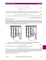
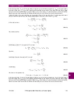
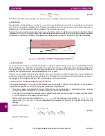
(EQ 9.50)
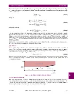
The last step assumes
, and replaces the phase current vector with its magnitude. This can be written as:
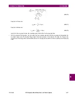
(EQ 9.51)
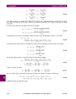
Alternatively, we can say:
(EQ 9.52)
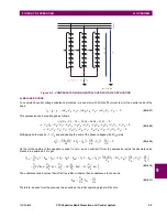
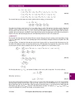
In the above equation,
Δ
C
(pu) represents the capacitance change as a per-unit of the string capacitance, and
I
OP
(
A
)
(pu)
represents the operating signal resulting from the failure in per-unit of the nominal current of the differential source.
I
A
is
phase A terminal current on the same base. When the system is normal (no fault),
I
A
may be taken as the capacitor bank
rated primary per-phase current
I
rated
converted to the differential source base. For example,
I
A
=
I
rated
/
I
base
, where
I
base
is again the differential CT primary current rating, or:
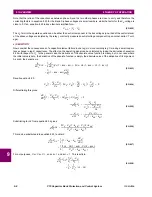
(EQ 9.53)
Note that under external fault conditions, sensitivity may be much different from the non-fault sensitivity.
d) AUTO-SETTING
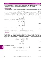
As a convenient alternative to manually determining inherent unbalance factor settings, the relay can automatically calcu-
late these settings from its own measurements while the capacitor is in-service, as described in the Commands section of
this manual. The technique the relay uses is to set the operate signal variable to zero in equation 8.43 and solve for the
inherent unbalance factor
k
A
using the average of several successive measurements of the currents. However, the
assumption made here is that when the auto-set command is executed, the capacitor is in an acceptably balanced state,
wherein the operating signal ought to be zero. Following the auto-set command, the protection will be measuring changes
from the state that existed at the time the auto-set command executed.
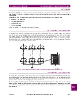
9.1.6 NEUTRAL CURRENT UNBALANCE (ANSI 60N)
a) OPERATING PRINCIPLE
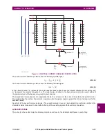
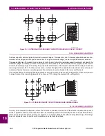
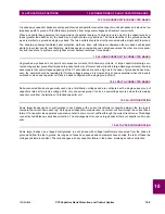
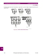
The neutral current unbalance function is based on the balance between interconnected neutral currents of two parallel
banks, and is applicable to both grounded and ungrounded installations. This text deals first with grounded applications,
with a section at the end that discusses the differences with ungrounded applications. A window CT measuring the vector
difference between the two neutral currents is required for grounded-wye configurations.
If the two banks were identical, the inter-neutral current would be zero. The failure of an element in either bank would then
result in inter-neutral current, which is sensed by the relay. However, with the two banks slightly mis-matched due to manu-
facturing tolerances, a circulating zero-sequence current may be present. Compensation for this inherent unbalance cur-
rent is available to increase the sensitivity of the function.
d
dC
A
1
--------------
I
OP A
( )
d
dC
A
1
--------------
I
A
C
A
1
C
A
2
–
C
A
1
C
A
2
+
---------------------------
×
k
A
I
A
–
⎝
⎠
⎛
⎞
=
I
A
C
A
1
C
A
2
+
(
)
C
A
1
C
A
2
–
(
)
–
C
A
1
C
A
2
+
(
)
2
---------------------------------------------------------------------
×
=
I
A
2
C
A
2
C
A
1
C
A
2
+
(
)
2
----------------------------------
×
=
I
A
2
----
1
C
A
1
----------
×
≅
C
A
1
C
A
2
≅
d
I
OP A
( )
I
A
2
----
d
C
A
1
C
A
1
--------------
×
=
I
OP A
( )
pu
(
)
I
A
2
----
C
pu
(
)
Δ
×
=
I
OP A
( )
pu
(
)
I
rated
2
I
base
----------------
C
pu
(
)
Δ
×
=
Summary of Contents for UR Series C70
Page 2: ......
Page 10: ...x C70 Capacitor Bank Protection and Control System GE Multilin TABLE OF CONTENTS ...
Page 344: ...5 220 C70 Capacitor Bank Protection and Control System GE Multilin 5 10 TESTING 5 SETTINGS 5 ...
Page 586: ...D 10 C70 Capacitor Bank Protection and Control System GE Multilin D 1 OVERVIEW APPENDIXD D ...

