


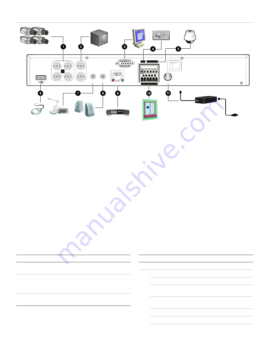
Figure 1: TVR 10 back panel connection diagram
1 3
4
2
VIN
VOUT
1
2
AIN
AOUT
ETHERNET
VGA
RS-485
ALARM IN
OUT
POWER
+12V
T+ T- R+R -
1 G
1
2
3
4
G G
P ow e r
L in k/ A ct
1 00
F D / C ol
1
2
3
4
5
6
7
8
1.
Connect up to four cameras
2.
Connect up to two CCTV monitors (one for main, two for spot)
3.
Connect to a VGA monitor
4. Alarm
output
5.
Connect to a PTZ control
6.
Connect to a USB mouse
7.
Connect to audio input
8.
Connect to speakers
9.
Connect to network devices
10. Connect to alarm input cables
11. Connect to the power supply
Turning on the TVR 10
Turn on the TVR 10 using the power switch on the back
panel. When you turn on the device, the TVR 10
automatically displays all live views from the connected
cameras. It also automatically begins recording.
Operating the TVR 10
LED indicators
The LED indicators on the front panel light up or flash to
alert you to various conditions.
Table 1: LED indicator descriptions
LED Description
Power
Steady green: The TVR 10 is powered up with no
error conditions.
HDD
Blinking red: Video is being recorded onto the hard
drive.
Solid red: The hard drive has an error.
Tx/Rx
Blinking green: Network data is being transferred to
or from the TVR 10.
Control options
There are several ways to control the TVR 10:
• Front panel control
• IR remote control
• Mouse menu control
• Web
browser
control
Tip:
A full range of alphanumeric characters is only
available when using the mouse or remote control.
Front panel control
The buttons on the front panel control most functions. See
Figure 3 on page 3 for locations of the controls.
Table 2: Front panel control descriptions
Item Control
Description
1
Status LEDs
Show the TVR 10 status. See Table 1 above.
2
Numeric buttons
Switch camera views and input numbers.
MENU
Accesses the main menu.
DISP
Displays multiscreen live mode. Accesses live
mode.
SRCH
Displays the Play Back screen for video
playback.
PTZ
Accesses the PTZ control mode.
LIVE
Displays Camera 1 in live mode.
REC
Displays the Manual Record screen.
2
TruVision DVR 10 Quick Start Guide


