background image

5

Hardware included

Carefully unpack and identify each part to make sure you 
have everything ready for installation. Lay out each part on 
a clean flat area such as a table or floor. Check to make sure 
you have the following:

A

2

E

2

I

1

C

2

G

15+1

15+1

K

1

N

2

B

2

F

J

1

M

1

D

2

H

4

L

1

O

6

ATTENTION: parts are not to scale.

Hardware Bag

Remote Control

PART

DESCRIPTION

Wood Screw (Long)

Spring Washer

Fibre Washer

Transmitter

Receiver

Mounting Screw

Flat Washer

Plastic Wire Nut

9 Volt Battery

Wood Screw (Short)

Star Washer

Blade Screw

Balance Kit

Transmitter Holder

Plastic Wire Nut

QUANTITY

A

E

I

C

G

K

N

B

F

J

M

D

H

L

O

Summary of Contents for Treviso 20314

Page 1: ... the Customer Care Service Team at 1 866 885 4649 Customer Service hours of operation are 9 00AM 5 00PM EST Monday Friday Treviso LED Ceiling Fan 52 in 1 32 m MODEL 20314 120V 60Hz MADE IN CHINA User Manual Customer Assistance 1 866 885 4649 ...

Page 2: ...g the fan or fan blades A dry dust cloth or lightly damped cloth will be suitable for cleaning 10 After making electrical connections spliced conductors should be turned upward and pushed carefully up into the outlet box The wires should be spread apart with the grounded conductor and the equipment grounding conductor on one side of the outlet box and ungrounded conductor on the other side of the ...

Page 3: ...ts each may be controlled by a separate wiring circuit 5 When replacing fuses turn off the main power first Make sure your hands and feet are dry and place one hand behind your back to prevent electricity from making a complete circuit through your chest Touch a plug fuse only by its insulated rim 6 Remove cartridge fuses with fuse puller 7 Use tools with insulated handles and ladders made of wood...

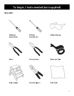
Page 4: ...4 To begin tools needed not supplied REQUIRED Flathead Screwdriver Pliers Step Ladder Phillips Screwdriver Wire Cutters Wire Strippers Safety Glasses Electrical Tape Soft Cloth ...

Page 5: ... the following A 2 E 2 I 1 C 2 G 15 1 15 1 K 1 N 2 B 2 F J 1 M 1 D 2 H 4 L 1 O 6 ATTENTION parts are not to scale Hardware Bag Remote Control PART DESCRIPTION Wood Screw Long Spring Washer Fibre Washer Transmitter Receiver Mounting Screw Flat Washer Plastic Wire Nut 9 Volt Battery Wood Screw Short Star Washer Blade Screw Balance Kit Transmitter Holder Plastic Wire Nut QUANTITY A E I C G K N B F J ...

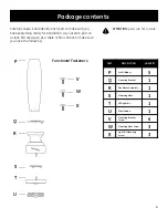
Page 6: ...ch as a table or floor Check to make sure you have the following P P 5 T T 1 1 4 X X 3 R R 1 V V Q Q 1 U U S S 1 W W 3 PART DESCRIPTION Set Of Blades Mounting Plate Mounting Bracket Screw Mounting Plate Screw Light Kit Mounting Screw Mounting Bracket LED light kit Fan Motor Assembly Glass Shade QUANTITY ATTENTION parts are not to scale Functional Fasteners ...

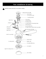
Page 7: ...Flat Washer Spring Washer Mounting Screw Ground Wire from Mounting Bracket Plastic Wire Nut Neutral White Wire Ground Wire from the Fan Motor Assembly Mounting Bracket Screw Blade Fibre Washer Blade Screw Mounting Plate Screw LED Light Kit Glass Shade Light Kit Mounting Screw Mounting Plate Fan Motor Assembly Black Wire Blue Wire White Wire Receiver Black Wire ...

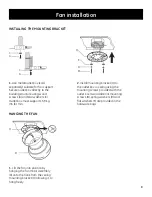
Page 8: ... washers C Outlet box must support 15 9 kg 35 lb min 1 Lift the fan into position by hanging the fan motor assembly R onto the hook from the ceiling mounting bracket Q allowing it to hang freely 2 Install mounting bracket Q to the outlet box in ceiling using the mounting screws provided with the outlet box two additional mounting screws B spring washers D and flat washers E are provided in the har...

Page 9: ...ose strands or connections PREPARING THE ELECTRICAL CONNECTIONS 1 This remote control unit is equipped with 16 code combinations to prevent possible interference from or to other remote units The frequency switches on your receiver M and transmitter J have been preset at the factory Please recheck to make sure the switches on the transmitter J and the receiver M are set to the same position any co...

Page 10: ...wire marked AC in N from the receiver Secure the wire connections with the plastic wire nuts H If your outlet box has a ground wire green or bare copper connect it to the ground wire from mounting bracket and ground wire from the fan motor assembly secure the wire connection with a plastic wire nut H otherwise connect the ground wire from the fan motor assembly to the ground wire from mounting bra...

Page 11: ... 3 light kit mounting screws X from the mounting plate S and keep it for future use Loosen the other 2 screws do not remove While holding the LED light kit T under the fan motor assembly make the 2 pin wire connections Red to red and black to black Place the key holes on the LED light kit T over the 2 light kit mounting screws X previously loosened turn the LED light kit T until it locks in place ...

Page 12: ... for warm weather operation Slide the switch to the right for cool weather operation Note wait for fan to stop before reversing the direction of the blade rotation 9 Select a location to install your Transmitter holder L Attach the transmitter holder L with the two short wood screws N provided 9 Vol t Ba tter y L N K J 4 0 button This button turns the fan off Speed settings for warm or cool weathe...

Page 13: ...not expressly approved by the party responsible for compliance could void the user s authority to operate the equipment Note This equipment has been tested and found to comply with the limits for a Class B digital device pursuant to part 15 of the FCC Rules These limits are designed to provide reasonable protection against harmful interference in a residential installation This equipment generates...

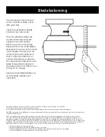
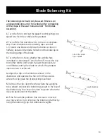
Page 14: ...increased or decreased Turn the fan off move the clip to another blade and retest Repeat this procedure on all blades noting the blade on which the greatest improvement is achieved 4 Adjust the clip on this blade as shown in the illustration and operate the fan to find the position where the clip gives the greatest improvement 5 Remove the clip clean the area where the weight is to be added and in...

Page 15: ...led ball bearings Check main and branch circuit fuses or breakers Check line wire connections to the fan and switch wire connections in the switch housing Check to make sure the dip switches from the transmitter and receiver are set to the same frequency Do not connect the fan with a wall mounted variable speed control s Make sure the dip switches are set correctly Make sure all motor housing scre...

Reviews: