
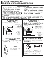

ALTERNATE EXHAUST DIRECTIONS
PAGE 3
Left knockout
Bottom
knockout
Right knockout
For Rear Exhaust
For Side Exhaust
Rigid
Metallic
Ducting
Cut Here
EXTENSION DUCT
It is importat to replace the ground clip after
cutting the exhaust duct, (on rear exhaust model).
Blower
Front of dryer
152 mm
295 mm
115 mm
203 mm
(8”)
89 mm
(3½”)
(4½”)
(11½”)
6”
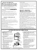
FOR BOTTOM EXHAUST:
Remove cover plate at bottom of dryer.
Install a 90° elbow.
Seal all joints with duct tape.
Reinstall rear access panel.
Place cover plate (removed from bottom of
dryer) over rear exhaust opening.
FOR SIDE EXHAUST:
Remove desired knockout plate (either right or
left side).
Cut a 115 mm (4 ½”) length of 100 mm (4”) dia
rigid duct as shown (remove burrs from cut
edge).
Attach this extension duct to blower housing duct.
Attach a 90° elbow facing desired opening.
Attach a section of 100 mm (4”) dia, rigid duct to
elbow to protrude through side of cabinet.
Seal all joints with duct tape.
Reinstall rear acces panel.
IF YOUR DRYER COMES WITH REAR
EXHAUST, TO CHANGE TO SIDE OR
DOWN EXHAUST:
Remove access panel at back of dryer to gain
access to internal ducts.
Disconnect duct exhaust from blower housing
(remove tape securing duct).
IF YOUR DRYER COMES WITH TOP EXHAUSTING,
TO CHANGE TO SIDE OR REAR EXHAUST:
Remove rear access panel.
Disconnect retaining plate & 90° elbow by removing
mounting screw from the chassis & remove tape securing
elbow to blower hounsing.
Remove cover plate from rear access panel and place over
top exhaust opening.
FOR SIDE EXHAUST:
Remove desired knockout plate (either right or left
side).
Cut a 115 mm (4 ½ “) lenght of 100 mm (4”) dia, rigid
duct as shown (remove burrs from cut edge).
Attach this extension duct to blower housing duct.
Attach the 90° elbow facing desired opening.
Attach a section of 100 mm (4”) dia, rigid duct to
elbow to protude thru side of cabinet.
Seal all joints with duct tape.
Reinstall rear access panel.
FOR REAR EXHAUST:
Cut a 295 mm (11 ½ “) length of 100 mm (4”) dia, rigid
duct as shown (remove burrs from cutting edge).
Attach this extension duct to blower housing.
Seal all joints with duct tape.
Reinstall near access panel.
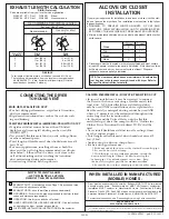
EXHAUST SYSTEM CHECK LIST
HOOD OR WALL CAP
• Terminate in a manner to prevent back drafts or entry of birds or
other wildlife.
• Termination should present minimal resistance to the exhaust air flow
and should require little or no maintenance to prevent clogging.
•
Never
install a screen in or over the exhaust duct. This could cause lint build up.
• Wall caps must be installed at least 12 in. above ground level or any other
obstruction with the opening pointed down.
SEPARATION OF TURNS
For best performance, separate all turns by at least 4 ft. of straight duct,
including distance between last turn and exhaust hood.
TURNS OTHER THAN 90º
• One turn of 45º or less may be ignored.
• Two 45º turns should be treated as one 90º turn.
• Each turn over 45º should be treated as one 90º turn.
SEALING OF JOINTS
• All joints should be tight to avoid leaks. The male end of each section of
duct must point away from the dryer.
• Do not assemble the ductwork with fasteners that extend into the duct.
They will serve as a collection point for lint.
• Duct joints can be made air and moisture-tight by wrapping the
overlapped joints with duct tape.
• Horizontal runs should slope down toward the outdoors ½ inch per foot
INSULATION
Duct work that runs through an unheated area or is near air conditioning
should be insulated to reduce condensation and lint build-up.
EXHAUST INFORMATION
WARNING - IN CANADA AND IN THE UNITED
IS 4 IN (102mm). DO NOT USE DUCT LONGER
STATES, THE REQUIRED EXHAUST DUCT DIAMETER
THAN SPECIFIED IN THE EXHAUST LENGTH TABLE.
Using exhaust longer than specified length will:
• Increase the drying times and the energy cost.
• Reduce the dryer life.
• Accumulate lint, creating a potential fire hazard.
The MAXIMUM ALLOWABLE duct length and number of
bends of the exhaust system depends upon the type of duct,
number of turns, the type of exhaust hood (wall cap), and all
conditions noted below. The maximum duct length for rigid
metal duct is shown in the table on the next page.
The correct exhaust installation is YOUR RESPONSIBILITY.
Problems due to incorrect installation are not covered
by the warranty.
Remove and discard existing plastic or metal foil transition
duct and replace with UL listed transition duct.
EXHAUST CONNECTION
WARNING - TO REDUCE THE RISK
OF FIRE OR PERSONAL INJURY:
•
•
•
•
•
•
•
•
•
•
This clothes dryer must be exhausted to the outdoors.
Use only 4” rigid metal ducting for the home exhaust duct.
Use only 4” rigid metal or UL-listed flexible metal (semi-
rigid or foil-type) duct to connect the dryer to the home
exhaust duct. It must be installed in accordance with the
instructions found in “Connecting The Dryer To House
Vent” on page 4 of this manual.
Do not terminate exhaust in a chimney, a wall, a ceiling, gas
vent, crawl space, attic, under an enclosed floor, or in any
other concealed space of a building. The accumulated lint
could create a fire hazard.
Never terminate the exhaust into a common duct with a
kitchen exhaust system. A combination of grease and lint
creates a potential fire hazard.
Do not use duct longer than specified in the exhaust length
table. Longer ducts can accumulate lint, creating a poten-
tial fire hazard.
Never install a screen in or over the exhaust duct. This will
cause lint to accumulate, creating a potential fire hazard.
Do not assemble ductwork with any fasteners that extend
into the duct. These fasteners can accumulate lint, creating
a potential fire hazard.
Do not obstruct incoming or exhausted air.
Provide an access for inspection and cleaning of the
exhaust system, especially at turns and joints. Exhaust
system shall be inspected and cleaned at least once a year.


