background image

CO

LD

HO

T

CO

LD

HO

T

Drain valve

9

Safety Instructions

Installation Instructions

Operating Instructions

Care and Cleaning

T

roubleshooting Tips

Customer Service

Thermal Expansion

Determine if a check valve exists in the inlet water line. Check with your local water
utility.

It may have been installed in the cold water line as a separate back flow preventer, or it

may be part of a pressure reducing valve, water meter or water softener. A check valve located in
the cold water inlet line can cause what is referred to as a 

“closed water system”

. A cold

water inlet line with no check valve or back flow prevention device is referred to as an 

“open”

water system.

As water is heated, it expands in volume and creates an increase in the pressure within the water
system. This action is referred to as 

“thermal expansion”

. In an 

“open”

water system,

expanding water which exceeds the capacity of the water heater flows back into the city main
where the pressure is easily dissipated.

“closed water system”

, however, prevents the expanding water from flowing back into the

main supply line, and the result of 

“thermal expansion”

can create a rapid and dangerous

pressure increase in the water heater and system piping. This rapid pressure increase can quickly
reach the safety setting of the relief valve, causing it to operate during each heating cycle.
Thermal expansion, and the resulting rapid, and repeated expansion and contraction of
components in the water heater and piping system can cause premature failure of the relief 
valve, and possibly the heater itself. Replacing the relief valve 

will not

correct the problem!

The suggested method of controlling thermal expansion is to install an expansion tank in the cold
water line between the water heater and the check valve (see illustration below). The expansion
tank is designed with an air cushion built in that compresses as the system pressure increases,
thereby relieving the over pressure condition and eliminating the repeated operation of the relief
valve. Other methods of controlling thermal expansion are also available. Contact your installing
contractor, water supplier or plumbing inspector for additional information regarding this subject.

Combustion Air
Inlet Openings

Water Supply Connections

Refer to the illustration below for suggested typical installation. The installation of unions or
flexible copper connectors is recommended on the hot and cold water connections so that the
water heater may be easily disconnected for servicing if necessary. The HOT and COLD water
connections are clearly marked and are 3/4” NPT on all models. Install a shut-off valve in the cold
water line near the water heater.

IMPORTANT: Do not apply
heat to the HOT or COLD
water connections. If sweat
connections are used,
sweat tubing to adapter
before fitting adapter to 
the cold water connections
on heater. Any heat applied
to the cold water supply
fittings will permanently
damage the dip tube.

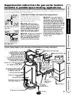
Typical Installation

Heat trap 
6” minimum

Heat trap 

6” minimum

Union

Hot water outlet

to fixtures

Temperature and

pressure relief valve

Relief valve
discharge line to
suitable open drain.

To gas supply

Cap

Jacket door

Auxiliary catch pan

Ground joint union

To cold water
supply

6” air gap

Draft hood

Pitch up 1/4”
per foot

Union

Thermostatic gas valve

Anode

Vent connector

to chimney

Manual gas shut-off

Shut-off valve

Thermal expansion
tank (if required)

Sediment trap

Shut-
off
valve

Drain Pan Pipe to

suitable drain

NOTICE: The National Fuel
Gas Code (NFGC)
mandates a manual gas
shut-off valve: See (NFGC)
for complete instructions.
Local codes or plumbing
authority requirements may
vary from the instructions
or diagrams provided and
take precedent over these
instructions.

Vacuum Relief Valve

(Not Supplied)

If required, install per local codes

and valve manufacturer’s

instructions.

Summary of Contents for SG Series

Page 1: ...nition System The purpose of this manual is twofold one to provide the installer with basic directions and recommendations for the proper installation and adjustment of the water heater and two for the owner operator to explain the features operation safety precautions maintenance and troubleshooting of the water heater This manual includes a parts list It is imperative that all persons who are ex...

Page 2: ...ate is needed to obtain service under the warranty IMPORTANT Fill out and return the Consumer Product Registration Card that is in the back of this manual If you do need service you can relax knowing help is only a phone call away For service call 800 431 1549 IF YOU NEED SERVICE Customer Service Troubleshooting Tips Care and Cleaning Operating Instructions Installation Instructions Safety Instruc...

Page 3: ...uate air supply for proper operation Be sure to inspect the vent system for proper installation at initial start up and at least annually thereafter Refer to the Care and Cleaning section of this manual for more information regarding vent system inspection DANGER INSTALL THE DRAFT HOOD AND PROPERLY VENT THE WATER HEATER Gasoline as well as other flammable materials and liquids adhesives solvents p...

Page 4: ...ure Dial DANGER Hotter water increases the Potential for Hot Water SCALDS D A N G E R HOT Water temperature over 125 F can cause severe burns instantly or death from scalds Children disabled and elderly are at highest risk of being scalded See instruction manual before setting temperature at water heater Feel water before bathing or showering Temperature limiting valves are available see manual BU...

Page 5: ...y federal state and or local laws rules regulations or customs LP gas must be used with great caution It is heavier than air and will collect first in lower areas making it hard to detect at nose level Before attempting to light the water heater make sure to look and smell for gas leaks Use a soapy solution to check all gas fittings and connections Bubbling at a connection indicates a leak that mu...

Page 6: ... a qualified technician SAFETY PRECAUTIONS IMPORTANT SAFETY INFORMATION READ ALL INSTRUCTIONS BEFORE USING WARNING For your safety the information in this manual must be followed to minimize the risk of fire or explosion electric shock or to prevent property damage personal injury or loss of life FOR INSTALLATIONS IN THE STATE OF CALIFORNIA California Law requires that residential water heaters mu...

Page 7: ... not allow the water heater to ignite until examined by a Qualified Service Technician The water heater must be located so it is not subject to physical damage for example by moving vehicles area flooding etc If local codes require the use of a stand kit to raise the water heater 18 above the floor please contact the store where the water heater was purchased or any water heater distributor These ...

Page 8: ...s directly or through vertical ducts there must be two openings located as specified above and each must have a minimum net free area of not less than one square inch per 4000 Btuh of the total input rating of all the appliances in the enclosure If horizontal ducts are used to communicate with the outdoors each opening must have a minimum net free area of not less than one square inch per 2000 Btu...

Page 9: ...ank is designed with an air cushion built in that compresses as the system pressure increases thereby relieving the over pressure condition and eliminating the repeated operation of the relief valve Other methods of controlling thermal expansion are also available Contact your installing contractor water supplier or plumbing inspector for additional information regarding this subject Combustion Ai...

Page 10: ...alve and discharge line The end of the discharge line should not be threaded or concealed and should be protected from freezing No valve of any type restriction or reducer coupling should be installed in the discharge line To Fill the Water Heater Make certain that drain valve is closed then open the shut off valve in the cold water supply line Open each hot water faucet slowly to allow the air to...

Page 11: ...s than 3 8 psi 10 5 w c for natural gas or 1 2 psi 14 w c for LP gas Gas Supply The branch gas supply line to the water heater should be clean 1 2 black steel pipe or other approved gas piping material A ground joint union or ANSI design certified semi rigid or flexible gas appliance connector should be installed in the gas line close to the water heater The National Fuel Gas Code NFGC mandates a ...

Page 12: ... Blankets Insulation blankets available to the general public for external use on gas water heaters are not necessary The purpose of an insulation blanket is to reduce the standby heat loss encountered with storage tank heaters This water heater meets or exceeds the National Appliance Energy Conservation Act standards with respect to insulation and standby loss requirements making an insulation bl...

Page 13: ...t the venting system complies with the guidelines found in the Use and Care Manual and National Fuel Gas Code DO contact a Qualified service technician if the pilot or main burner will not stay lit The burner chamber is designed to be sealed utilizing a gasket and tamper resistant screws DON T DON T block or restrict Combustion Air Inlet Openings located around the lower portion of the water heate...

Page 14: ...ent room to service heater Combustible materials such as clothing cleaning materials rags etc clear of the base of the heater Clearances from combustion air inlet openings observed see page 7 Gas Supply Gas line equipped with shut off valve union and sediment trap Approved pipe joint compound used Soap and water solution used to check all connections and fittings for possible gas leak Gas Company ...

Page 15: ...ic chemicals such as those used for boiler treatment into this system Tee fitting for horizontal hot water supply lines Hot water supply to house From HOT outlet on water heater From HOT outlet on water heater Hot water supply to heating unit Hot water supply to house Hot water supply to heating unit R E L I E F V A L V E C O L D H O T C O L D H O T Typical Piping Diagram for Combination Potable S...

Page 16: ...r heater be sure to read and follow the instructions on the label pictured below and all other labels on the water heater as well as the warnings printed in this manual Failure to do so can result in unsafe operation of the water heater resulting in property damage personal injury or death Should you have any problems reading or following the instructions in this manual STOP and get help from a qu...

Page 17: ...ops to accumulate near water heater Do Not store or use gasoline or other flammable vapors and liquids such as adhesives or paint thinner in vicinity of this or any other appliance If such flammables must be used open doors and windows for ventilation and all gas burning appliances in the vicinity should be shut off including their pilot burners to avoid vapors lighting NOTICE Flammable vapors can...

Page 18: ...aken The hottest temperature water will be at the top of the tank closest to the outlet pipe delivering hot water to the home Stacking can cause this top layer of water to be hotter than the water toward the bottom of the tank near the gas control thermostat Therefore always remember to test the water temperature with your hand before use and remember that hotter water increases the risk of scald ...

Page 19: ...ars of dependable trouble free service It is recommended that a periodic inspection of the gas control thermostat burner relief valve internal flue way and venting system should be made by service personnel qualified in gas appliance repair It is suggested that a routine preventative maintenance program be established and followed by the user At least once a year lift and release the lever handle ...

Page 20: ...ng shut down period the water heater s operation and controls should be checked by qualified service personnel Make certain the water heater is completely filled again before placing it in operation NOTICE Do not remove the anode rod from the water heater s tank except for inspection and or replacement as operation with the anode rod removed will greatly shorten the life of the glass lined tank an...

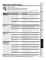
Page 21: ...ced by a clogged qualified service technician Gas Cock Knob not See the Lighting The Water Heater section of this correctly positioned manual Pilot does not stay Loose thermocouple The connection at the gas control thermostat should lit when the RED be tightened by a qualified service technician button is released Thermocouple defective The thermocouple should be replaced by a qualified service te...

Page 22: ...cessary relight using the instructions in the Lighting The Water Heater section of this manual The gas control thermostat See the Water Temperature Setting of The Water may be set too low Heater section of this manual Leaking or open hot water Make sure all faucets are closed faucets Combustion Shutoff System Contact a qualified service technician tripped Water is too hot The gas control thermosta...

Page 23: ...Safety Instructions Installation Instructions Operating Instructions Care and Cleaning Troubleshooting Tips Customer Service 23 Notes ...

Page 24: ...Customer Service Troubleshooting Tips Care and Cleaning Operating Instructions Installation Instructions Safety Instructions 24 Notes ...

Page 25: ...y Tube The kit provides extra speed clips and tamper resistant screws Not supplied with all models Burner Assembly Kit Heat Trap Nipple Heat Trap Nipple Replacement parts For 30 40 and 50 gallon models using natural or LP gas Instructions For Placing a Parts Order To place orders using a Visa MasterCard call 800 431 1549 All parts orders should include The model and serial number of the water heat...

Page 26: ... Manufacturer s National Service Department at the following address 2600 Gunter Park Drive Montgomery AL 36109 1413 When contacting the manufacturer the following information will be requested Model and serial number of the water heater as shown on the rating plate attached to the jacket of the heater Address where the water heater is located and physical location Name and address of installer an...

Page 27: ...Rheem Manufacturing Company Warranty Registration Department P O Box 34070 Louisville KY 40232 4070 Please place in envelope and mail to Cut here Cut here 27 ...

Page 28: ...Mrs Miss Street Address City State Date Placed In Use Month Day Year Zip Code Apt Last Name Phone Number _ _ Complete and mail this Consumer Product Ownership Registration today After mailing the registration below store this document in a safe place It contains information you will need should you require service Read your Use and Care Manual carefully It will help you operate your new appliance ...

Reviews: