GE Healthcare
Senographe DS
Revision 1
Service Information and Procedures Class A 2385072-16-8EN
Job Card ELE A005 - Check Supply Voltages
Page no. 541
Chapter 7
JC-ELE-A-005.fm
Job Card ELE A005 - Check Supply Voltages
Chapter 7
1
SUPPLIES
None
2
TOOLS
3
SAFETY PRECAUTIONS
None
4
REQUIRED EFFORT
Personnel: 1 Field Engineer
Time: 40 minutes
5
PREREQUISITES
The procedures described in
Job Card PHY A016 - AC Connection
must have been completed cor-
rectly.
6
FIRST POWER-ON CHECK
You must detect incorrect mains supply configuration - before it is too late!
6-1
Check the Keep-Alive Supply Voltage
1. Check that generator Mains Supply Switch 200-S1 is open
(i.e. in the "0" position).
2. Check that the Mains Distribution Rack circuit breaker is open
(i.e. in the ”0” position).
3. Close the main hospital supply circuit breaker.
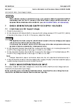
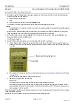
4. Connect the multimeter (set to 20 VDC scale) to the Mains
Distribution Board 200-PL1 between test points PT15 (+V
E
)
and PT12 (0V
E
). See illustration.
5. Close generator Mains Supply Switch 200-S1 (i.e., turn it to
the ”1” position) and read the multimeter immediately. It must
read +8 ±2 VDC.
CAUTION
If the voltmeter reading is outside this range, turn mains source off immediately. Then
check the configuration of voltage selection board IN2 on the Generator Mains Distribution
Board 200-PL1 (see
Job Card PHY A016 - AC Connection
6. Move the multimeter from PT15 (+V
E
) to PT14 (-V
E
). The multimeter must read -8V ± 2 VDC.
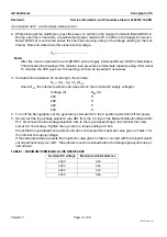
7. Connect the multimeter (set to 500 VAC scale) to the Generator Mains Power Board 200-PL1
between terminals 1 (0 V) and 4 (220 V).
8. Turn on the X-ray Console and read the multimeter immediately. It must read 220 ± 20 VAC.
PT14
PT15
X1
TR2
R1
R4
PT12
- VE
+ VE
0V
E
+V
E
POWER BOARD 200-PL1

