GE RAB46 Installation Instructions Manual Download Page 4

Specifications subject to change without notice 

A Quality Product of GE Appliances

4

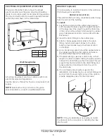
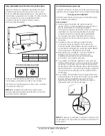
ELECTRICAL REQUIREMENTS (230V/208V)

Provisions should be made to have the proper 

electrical outlet near the case. All wiring should be 

made in accordance with local codes and regulations. 

The line cord will extend to a wall receptacle located 

within the area shown in the table below.

Wall Receptacles

All wiring should be made in accordance with local 

electrical codes and regulations.
See the Owner’s Manual for how to connect electrical 

supply. 

NOTE: 

Aluminum wiring in structure may pose 

special problems—consult a qualified electrician.

A

Inside

120V/115V 12 amp

230V/208V 20 amp

“tandem” type

“perpendicular” type

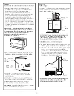
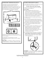
DRAIN KIT (optional)

If it is necessary to install a drain kit on this wall case, 

the following kit is available:

RAD4A1 External Drain

This external drain will carry condensate water away 

from the unit and the building.

To install:
1. 

Cut off the solid end of the rubber plug (approx. 

1/8

). Be sure the hole is open through the length 

of the plug. Insert the plug through the drain hole 

in the corner of the cabinet. (Immersing the rubber 

plug in denatured alcohol or soap suds will make 

this easier.)

2. 

Insert the drain fitting into the rubber plug.

3. 

Attach a field-supplied drain tube to the drain 

fitting. Install strain relief clamps to the drain  

tube to prevent leaks due to mechanical strain  

or vibration.

4. 

A non-hardening sealant should be applied where 

the rubber plug fits into the cabinet and where  

the drain fitting meets the rubber plug.

5. 

If metallic tubing is used as a drain tube, a short 

length of rubber or plastic tubing should be used to 

connect the drain fitting to the drain tube. This will 

prevent mechanical strain to the drain fitting and 

reduce vibration transmission from the unit to  

the drain tube. 

6. 

If an architectural rear grille is used in this 

installation, it is necessary to cut a small triangular 

section from the lower right corner of the grille to 

provide adequate space for the drain tube.

NOTE: 

It may be desirable or necessary to install 

the drain kit on the case prior to installing the case 

into the wall.

Cabinet

Rubber  

plug

Drain 

fitting

  MODEL 

“A” 

“B”


115V


47

″ 

72


230/208V  39


65

B

Summary of Contents for RAB46

Page 1: ...n of case into room 1 4 min If more than 6 of the case projects into the room other support is recommended C Projection of case to outside 1 4 min D Height above finished floor or top of carpet 0 min E Left Right side of case to adjacent wall 2 min 31 61545 GE 09 28 09 INSTALL CASE LEVEL IN ALL DIRECTIONS NOTE Handle the case carefully CASE LOCATION As a general rule the air conditioner should be ...

Page 2: ...vertically on each side of the case to provide a level installation 2 Mark the case through the holes in the case angles 3 Drill 5 32 diameter holes at marked locations on the case and assemble the angles using only 10 1 2 screws Install the screws from the outside of the case NOTE Do not drill any holes in bottom of the case MINIMUM FINISHED OPENING DIMENSIONS CASE DIMENSIONS Height Width Height ...

Page 3: ...d the building interior Use lintel when required to support brick and block above the case NOTE Do not drill any holes in the case for electrical connections STEP 4 Weatherproofing Weatherproof gaps between the exterior and interior walls and the case with caulking or equivalent weatherproofing material NOTE It is critical to caulk around perimeter of wall case on all four sides on the outside and...

Page 4: ...open through the length of the plug Insert the plug through the drain hole in the corner of the cabinet Immersing the rubber plug in denatured alcohol or soap suds will make this easier 2 Insert the drain fitting into the rubber plug 3 Attach a field supplied drain tube to the drain fitting Install strain relief clamps to the drain tube to prevent leaks due to mechanical strain or vibration 4 A no...

Page 5: ... été installé DÉGAGEMENT RECOMMANDÉ DIMENSIONS POUR L INSTALLATION A Entre le dessus du boîtier et le plafond fini 7 6 cm 3 po min B Partie saillante du boîtier dans la pièce 6 mm 1 4 po min Si la partie saillante du boîtier dans la pièce est de plus de 15 2 cm 6 po il est recommandé d utiliser un autre type de support C Partie saillante du boîtier à l extérieur 6 mm 1 4 po min D Hauteur au dessus...

Page 6: ...10 2 cm 4 po x 4 po ou deux pièces de 5 1 cm x 10 2 cm 2 po x 4 po sur le chant Sous plancher Poteaux nains Poteau nain Ajustez la charpente afin d obtenir cette dimension Voir le tableau de la page 1 Plancher fini DIMENSIONS MINIMALES DE L OUVERTURE DIMENSIONS FINIE DU BOÎTIER Hauteur Largeur Hauteur Largeur Profondeur 41 cm 66 3 cm 39 7 cm 66 2 cm 40 6 cm 153 4 po 261 8 po 155 8 po 261 16 po 16 ...

Page 7: ...ntre le boîtier et le mur intérieur de l immeuble Au besoin installez un linteau pour soutenir les briques et les blocs au dessus du boîtier REMARQUE Ne percez pas de trous dans le boîtier pour les raccordements électriques ÉTAPE 4 Calfeutrage Calfeutrez les jeux entre les murs intérieur et extérieur et le boîtier à l aide d un calfeutre ou d un matériau d étanchéité équivalent REMARQUE Il est trè...

Page 8: ...n Insérez le bouchon à travers le trou d écoulement dans le coin du boîtier L immersion du bouchon en caoutchouc dans l alcool dénaturé ou dans l eau de savon facilitera l insertion 2 Insérez le raccord d écoulement dans le bouchon en caoutchouc 3 Fixez un tube d écoulement acheté localement sur le raccord Installez des brides à décharge de tension sur le tube pour prévenir les fuites causées par ...

Page 9: ... la pared donde no haya cableado eléctrico o tuberías de agua y donde no haya obstrucciones cercanas ya sea adentro o afuera DIMENSIONES CRÍTICAS NOTA Debe tenerse cuidado al ubicar la entrada de suministro eléctrico en relación con la funda de la pared para garantizar acceso a la energía una vez que se haya instalado la unidad DIMENSIONES ESPACIO DE INSTALACIÓN RECOMENDADO A Parte superior de la ...

Page 10: ...nas Viga Ajuste el armazón para asegurar esta dimensión Ver la tabla de la página 1 Piso terminado Las dimensiones pueden tener que incrementarse para adecuarse a situaciones únicas en el campo si se utilizan ángulos de la caja DIMENSIONES DE ABERTURAS MÍNIMAS DIMENSIONS TERMINADAS DU BOÎTIER Altura Ancho Altura Ancho Profundidad 153 4 261 8 155 8 261 16 16 41 cm 66 3 cm 39 7 cm 66 2 cm 40 6 cm PA...

Page 11: ...ja dentro de la pared Consulte la tabla de la página 1 sobre proyección del lado de la habitación El extremo trasero externo de la caja debe extenderse por lo menos 1 4 6 mm más allá de la pared exterior para poder efectuar el calafateo correctamente y para prevenir el sellado de los orificios de drenaje en la brida trasera de la caja y para facilitar una instalación sencilla de una drenaje acceso...

Page 12: ...ón Introduzca el tapón a través del orificio de drenaje ubicado en la esquina del gabinete Sumergir el tapón de goma en alcohol desnaturalizado o en espuma de jabón facilitará esta acción 2 Introduzca el accesorio de drenaje en el tapón de goma 3 Conecte el tubo de drenaje proporcionado en el lugar de la instalación al accesorio de drenaje Instale abrazaderas de alivio de tensión en el tubo de dre...

Reviews: