


– 31 –
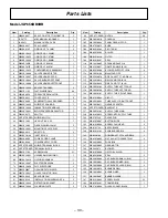
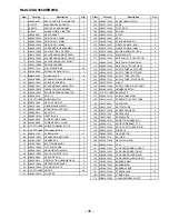
Model JGP656WB0WW
View
Catalog
Description
Qty.
1
WB02X9857
SEAL-COOKTOP TO WORKTOP
2
1
31-20775
MINI-MANUAL (SNORKEL)
1
1
49-80011
PM USE & CARE MANUAL
1
2
WB02X9857
SEAL GASKET
4
3
WB28K0145
ORIFICE LP .78 LMM
2
3
WB28K10022
ORIFICE-NG 1.50MM
2
3
WB28K10029
ORIFICE-NG 1.07MM
1
3
WB28K10030
ORIFICE-NG 1.68MM
1
3
WB28K10031
ORIFICE-LP .63MM
1
3
WB28K10107
ORIFICE SPUD LP .84MM
1
4
WB63K10022
CONTAINER BOX ASSEMBLY
1
8
WB21K10006
VALVE BURNER LFT RR
1
9
WB21K10007
VALVE BURNER RT RR
1
10
WB21K10005
VALVE BURNER RT FRONT
1
11
WB21K10008
VALVE BURNER LEFT FRONT
1
13
WB02K10036
BRACKET BURNER
4
14
WB01X1192
FLAT WASHER-M4
30
16
WB19K0026
PRESSURE REGULATOR
1
18
WB02K0108
COVER VALVE
5
21
WB01K0083
SCREW-MTG VALVE BURNER
5
30
WB34K10042
SHIELD SPARK MOD
1
31
WB35K10023
INSULATION-SPK MODULE
1
38
WB24K10001
BLOWER SPEED REGULATOR
1
40
WB24X0475
SWITCH
1
42
NOT STOCKED SHIELD-SWITCH
1
44
WB01X1382
HEX NUT 3/8" X 32
1
48
WB01X1383
FIBRE WASHER 10MM
2
50
WB02K10001
MOUNTING PLATE ELEC
1
51
WB06K0014
ADAPTOR
1
52
WB28K10106
INLET BLOCK
1
54
WB02X9836
GROUND POST ASSEMBLY
1
56
WB02X9838
POWER CORD CLAMP
1
58
WB18X0380
POWER SUPPLY CORD
1
60
NOT STOCKED SHIELD-TERMINAL BLOCK
1
62
NOT STOCKED TERMINAL BLOCK
1
64
WB01X1189
SCREW M4X8
21
66
WB18K10001
HARNESS-MAIN WIRING
1
66
WB18K10010
HV WIRE HARNESS
1
72
WB13K10007
ELECTRODE SPARK
5
74
WB01K10026
CLIP ELECTRODE
5
75
WB02K10037
GROUND PATH SHIELD
5
86
WB57K10052
GLASS COOKTOP-WH
1
88
WB02X9843
SEAL-DRIP PAN
5
91
WB02X9243
INSTALLATION HARDWARE PK
2
94
WB02K10044
RETENTION BRACKET
5
95
WB34K10043
CLAMPING PLATE
5
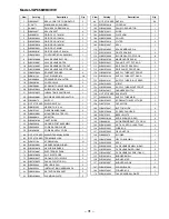
View
Catalog
Description
Qty.
96
NOT STOCKED NUT M4
30
101
WB56X10010
COVER 36"
1
102
WB56X10004
PANEL GEAR MOTOR
1
103
WB07X10012
SLIDE
1
104
WB02X10303
PIVOT ARM
1
106
WB02X10306
ROLLER
1
108
WB02X10310
FILTER
2
109
WB02X10307
SEAL
1
110
WB13K10005
SPARK MODULE 5+0
1
112
WB31K10059
GRATE DOUBLE
2
113
WB02X10308
BLOWER SUPPORT LEGS
8
114
WB28K10108
MANIFOLD PIPE ASM
1
115
WB32K10021
PAN UNIT LEFT FRT & RR
2
115
WB32K10022
DRIP PAN RT REAR WH
1
115
WB32K10024
DRIP PAN RT FRONT WH
1
116
WB28K10102
SUPPLY TUBE-LEFT FRONT
1
118
WB28K10100
SUPPLY TUBE-LEFT REAR
1
122
WB28K10101
SUPPLY TUBE -RIGHT REAR
1
123
WB01X10004
U-BOLT
1
124
WB28K10099
SUPPLY TUBE-RIGHT FRONT
1
125
WB18K10011
HARNESS SWITCH
1
126
NOT STOCKED BASEPLATE
1
127
WB28K10105
SUPPLY TUBE MAIN
1
128
WB01K10025
SCREW-MTG SUPPLY TUBE
1
129
WB27X5599
CAPACITOR
1
133
WB01X10007
BUTTON SLIDE
4
135
WB01X10008
SCREW, PAN HEAD
2
138
WB07X1832
BEZEL-WHITE
5
140
WB03K10106
KNOB BURNER (GRAY)
4
142
WB03K0103
KNOB-DOWNDRAFT CTL GRAY
2
145
WB01K10005
NUT 6-32- MTG GLASS TRIM
4
146
WB34K10002
WIRE BOX
1
147
WB26X10005
GEAR MOTOR
1
148
WB38X5079
BLOWER
1
149
WB01X10006
HEYCO BUSHING
1
150
WB02X10309
SEAL
2
151
WB29K10002
CAP-BURNER SMALL (GRAY)
1
152
WB29K10004
CAP-BURNER MED (GRAY)
2
153
WB29K10007
CAP-BURNER LARGE (GRAY)
1
155
WB16K10014
BURNER-SMALL
1
156
WB16K10005
BURNER-MED
2
157
WB16K10007
BURNER-LARGE
1
167
WB01X10003
SCREW BLACK
25
169
WB02X10301
FORMED BOX
1
170
WB61K10002
GLASS-SNORKEL-WHITE
1