background image

3

Installation Instructions

PREPARE THE OPENING

See illustrations for all rough-in and spacing
dimensions.

The range may be placed with 0” clearance
(flush) at the back wall and side walls of 
the cabinet.

NOTE: 

Use a 4

power cord to prevent

interference with the storage drawer. 
Power cords 4

1

2

to 6

long may have to be

dressed to allow for proper drawer closing.

MINIMUM DIMENSIONS BETWEEN COOKTOP,
WALLS AND ABOVE THE COOKTOP:

**

*

Make sure the wall covering, countertop,
flooring and cabinets around the range 
can withstand the heat (up to 200°F) 
generated by the range.

*

**

Allow 30” minimum clearance between
surface units and bottom of unprotected
wood or metal cabinet, and 15” minimum
between countertop and adjacent cabinet
bottom.

***

Recommended spacing to heat-sensitive
surfaces.

2

2

1

2

2

1

2

7

1

2

25”

36”

30”

Acceptable electrical
outlet area. 

Orient the electrical
receptacle so the length
is parallel to the floor.

*0”

**15” Min.

**30” Min.

*0”

***6”

Min.

7”

14

1

2

On models with baking or
warming drawers, electrical
outlet must not be in this
area.

Summary of Contents for Profile JB900TKWW

Page 1: ...ng the installation switch power off at service panel and lock the service disconnecting means to prevent power from being switched on accidentally When the service disconnecting means cannot be locke...

Page 2: ...t be no deeper than 13 Be sure your appliance is properly installed and grounded by a qualified technician Make sure the cabinets and wall coverings around the range can withstand the temperatures up...

Page 3: ...VE THE COOKTOP Make sure the wall covering countertop flooring and cabinets around the range can withstand the heat up to 200 F generated by the range Allow 30 minimum clearance between surface units...

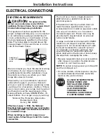
Page 4: ...CAL REQUIREMENTS CAUTION For personal safety do not use an extension cord with this appliance Remove house fuse or open circuit breaker before beginning installation This appliance must be supplied wi...

Page 5: ...train relief they can be removed for better fit NOTE Do not install the power cord without a strain relief The strain relief bracket should be installed before reinstalling the rear range wiring cover...

Page 6: ...ral is connected to the center lower position of the terminal block Tighten screws securely into the terminal block Skip to Step 8 and proceed with the installation E D C B A 5 3 WIRE POWER CORD INSTA...

Page 7: ...ocal codes Skip to Step 8 and proceed with the installation B A 6 4 WIRE CONDUIT INSTALLATION Loosen the three lower terminal screws from the terminal block Remove the ground screw and ground plate an...

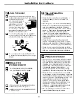
Page 8: ...liquids or from the range itself 9 Typical installation of anti tip bracket attachment to wall Bracket Screw must enter wood or metal Wall plate REPLACE THE WIRE COVER Replace the wire cover on the ra...

Page 9: ...door and drawer are parallel to each other and that both operate smoothly If they do not see the Owner s Manual for proper replacement Check to make sure that the rear leveling leg is fully inserted...

Page 10: ...10 Notes...

Page 11: ...11 Notes...

Page 12: ...12 Printed in the United States...

Reviews: