Installation Instructions
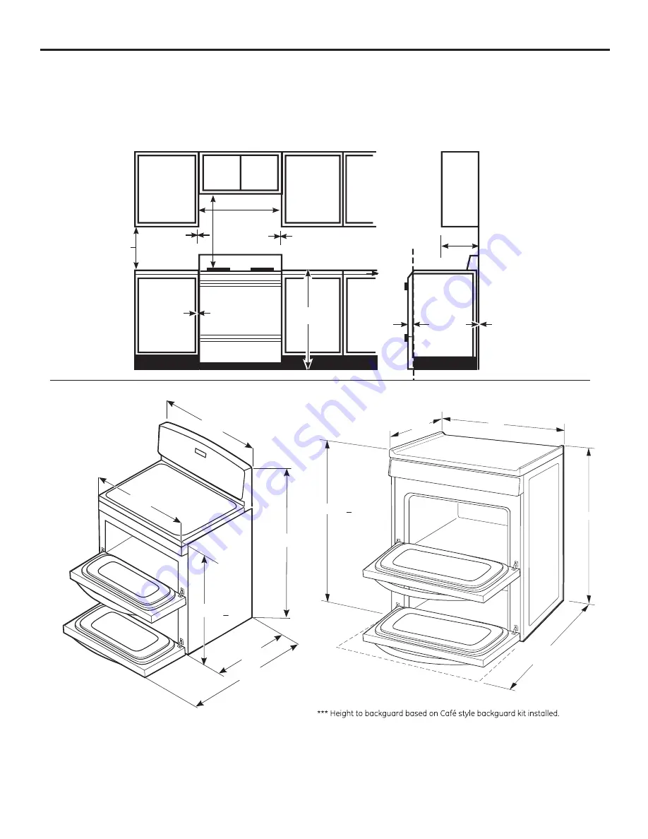
Provide adequate clearances between the range and adjacent combustible surfaces. These dimensions must be
met for safe use of your range. The location of the electrical outlet and pipe opening (see Gas Pipe and Electric
Outlet Locations) may be adjusted to meet specific requirements.
The range may be placed with 0
″
clearance (flush) at the back wall.
DIMENSIONS AND CLEARANCE
.40
**43-3/4”
48”
*29-3/4”
36-1/4” +1/4”
30”
30 3/4”
* Dimension includes handle with doors closed.
**Dimension are referenced from the point at
the back of the range that will contact the rear wall first.
Max dimension should be considered between the upper
and lower doors.
*29.1/4"
36.1/4".+1/4"
***41.1/2"
**43.3/8"
Depth.with.door.open
30"
To.cabinets.below.
cooktop.and.at.
the.range.back
To.cabinets.
below.
cooktop.and.
at.the.range.
back
30”
30”
6”
Minimum
13”
Minimum.
clearance.to.
right.wall
Maximum.
depth.for.
cabinets.above.
countertops
Front.edge.of.
the.range.side.
panel.forward.
from.cabinet
18”
0”
1/4”
Minimum.to.
cabinets.on.
either.side..
of.the.range
36”
6”
Minimum.
clearance..
to.left.wall*
0”
Summary of Contents for PCGB995
Page 55: ...55 Notes GEAppliances com...


