Chapter 1. Introduction
GFK-2571N
May 2018
21
1.6.6
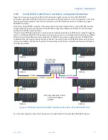
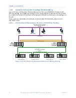
One RX3i CPU with Four Controllers on Separate Networks
Figure 11 shows a system with one RX3i CPU node containing the maximum of four RX3i PROFINET
Controllers, with each PROFINET Controller connected to a different network. In this architecture, up to 255 IO-
Devices are allowed, spread across the four networks. Up to 128 IO-Devices can be controlled by any given
PROFINET Controller.
Note that multiple PNC001 modules in the same rack are not synchronized; that is, no two PNC001 modules
are guaranteed to power up at the same time. PNC001 configuration differences (SFPs, etc.) can also cause
variations in PNC001 power-up times.
If two (or more) PNC001 modules are in a main rack and devices owned by one PNC001 are routed through the
switch on a different PNC001 in the same rack, devices may show a
Loss of Device
fault followed by an
Addition
of Device
fault during RX3i power-up because the first PNC001 can power up before the second PNC001 has
enabled its Ethernet switch, causing the
Loss of Device
. Then when the second PNC001 powers up, the device
will show an
Addition of Device
fault, which is to be expected under these circumstances. Devices will function
normally once added.
IO-Device
IO-Device
IO-Device
IO-Device
IO LAN 1
IO-Device
IO-Device
IO-Device
IO-Device
IO LAN 2
IO LAN 4
IO LAN 3
RX3i CPU Node
with four PNCs
Daisy chain shown for clarity.
A star or ring topology is
preferred.
Note:
Figure 11: RX3i System with four PNC001 modules and four Daisy-Chain PROFINET LANs
As in the other examples, other GE IO-Devices can be substituted for the VersaMax PROFINET Scanners.

