background image

GE C

OMPANY

D

IRECTION

 5472001-1EN, R

EVISION


6

O

PTIMA

 CT680 S

ERIES


AND

 O

PTIMA

 CT670 I

NSTALLATION

 M

ANUAL

Page 114  

Section 3.0 - Console Connections
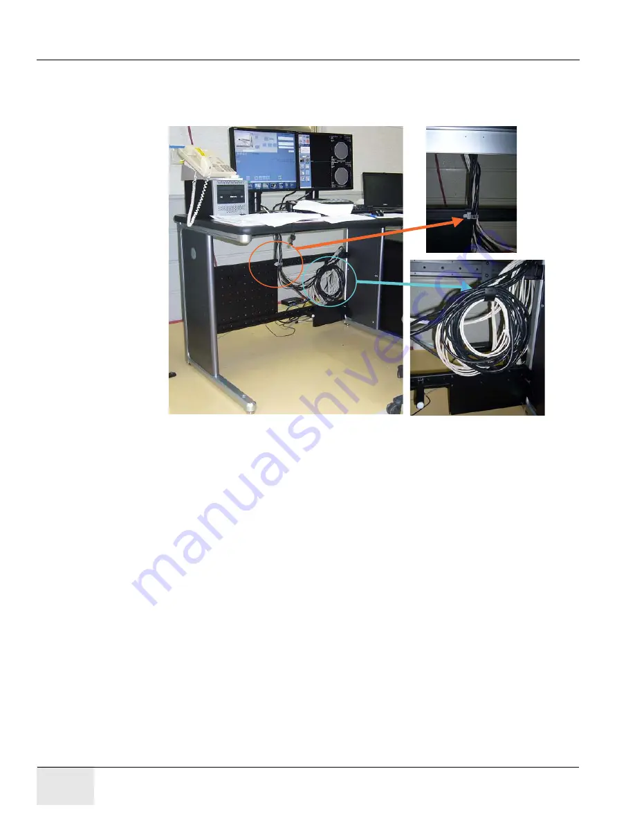
3.7

Cable Arrangement

Arrange the cables appropriately by using the cable clamps equipped on the console tables.

Figure 2-17 Example: Cable Arrangement

Summary of Contents for Optima CT670

Page 1: ...OPERATING DOCUMENTATION 5472001 1EN Rev 6 Optima CT680 Series and Optima CT670 Installation Manual Book 1 of 2 ...

Page 2: ...IES AND OPTIMA CT670 INSTALLATION MANUAL Page 2 Book 1 of 2 Mechanical Installation Pages 1 206 Effectivity The information in this manual applies to the following Optima CT Systems Optima CT680 Quantum Optima CT680 Expert Optima CT680 Professional Optima CT670 ...

Page 3: ...危險 警告 ZH TW 本維修手冊僅有英文版 若客戶的維修廠商需要英文版以外的語言 應由客戶自行提供翻譯服 務 請勿試圖維修本設備 除非 您已查閱並瞭解本維修手冊 若未留意本警告 可能導致維修廠商 操作員或病患因觸電 機械或其 他危險而受傷 UPOZORENJE HR Ovaj servisni priručnik dostupan je na engleskom jeziku Ako davatelj usluge klijenta treba neki drugi jezik klijent je dužan osigurati prijevod Ne pokušavajte servisirati opremu ako niste u potpunosti pročitali i razumjeli ovaj servisni priručnik Zanemarite li ovo ...

Page 4: ... may result in injury to the service provider operator or patient from electric shock mechanical or other hazards HOIATUS ET See teenindusjuhend on saadaval ainult inglise keeles Kui klienditeeninduse osutaja nõuab juhendit inglise keelest erinevas keeles vastutab klient tõlketeenuse osutamise eest Ärge üritage seadmeid teenindada enne eelnevalt käesoleva teenindusjuhendiga tutvumist ja sellest ar...

Page 5: ... igényt akkor a vevő felelőssége a fordítás elkészíttetése Ne próbálja elkezdeni használni a berendezést amíg a karbantartási kézikönyvben leírtakat nem értelmezték Ezen figyelmeztetés figyelmen kívül hagyása a szolgáltató működtető vagy a beteg áramütés mechanikai vagy egyéb veszélyhelyzet miatti sérülését eredményezheti AÐVÖRUN IS Þessi þjónustuhandbók er aðeins fáanleg á ensku Ef að þjónustuvei...

Page 6: ...ninių ar kitų pavojų ADVARSEL NO Denne servicehåndboken finnes bare på engelsk Hvis kundens serviceleverandør har bruk for et annet språk er det kundens ansvar å sørge for oversettelse Ikke forsøk å reparere utstyret uten at denne servicehåndboken er lest og forstått Manglende hensyn til denne advarselen kan føre til at serviceleverandøren operatøren eller pasienten skades på grunn av elektrisk st...

Page 7: ...ническому обслуживанию представлено только на английском языке Если сервисному персоналу клиента необходимо руководство не на английском а на каком то другом языке клиенту следует самостоятельно обеспечить перевод Перед техническим обслуживанием оборудования обязательно обратитесь к данному руководству и поймите изложенные в нем сведения Несоблюдение требований данного предупреждения может привест...

Page 8: ...ervice på utrustningen om du inte har läst och förstår den här servicehandboken Om du inte tar hänsyn till den här varningen kan det resultera i skador på serviceteknikern operatören eller patienten till följd av elektriska stötar mekaniska faror eller andra faror OPOZORILO SL Ta servisni priročnik je na voljo samo v angleškem jeziku Če ponudnik storitve stranke potrebuje priročnik v drugem jeziku...

Page 9: ...field engineers All of GE s electrical work on these products will comply with the requirements of the applicable electrical codes The purchaser of GE equipment shall only utilize qualified personnel i e GE s field engineers personnel of third party service companies with equivalent training or licensed electricians to perform electrical servicing on the equipment IMPORTANT X RAY PROTECTION X ray ...

Page 10: ...s been removed and replaced See Radiation Survey Form Instructions or contact your EHS Specialist Rev 2 July 21 2005 LITHIUM BATTERY CAUTIONARY STATEMENTS CAUTION Risk of Explosion Danger of explosion if battery is incorrectly replaced Replace only with the same or equivalent type recommended by the manufacturer Discard used batteries according to the manufacturer s instructions ATTENTION Danger d...

Page 11: ...Added Figure 8 8 for z840 rear panel connection 4 May 20 2016 Chapter 2 Section 3 1 Added keyboard overlay installation information Update Figure 2 5 and Table 2 5 for GSCB connection Section 3 2 Added PMT 22 information 3 Sep 06 2015 Chapter 1 Section 5 4 Updated Figure 1 5 Chapter 1 Section 11 Added information of 5487992 2 Anchor 2 April 09 2014 Chapter 2 Updated Table 2 3 system interconnect c...

Page 12: ...GE COMPANY DIRECTION 5472001 1EN REVISION 6 OPTIMA CT680 SERIES AND OPTIMA CT670 INSTALLATION MANUAL Page 12 Revision History ...

Page 13: ...se and Transportation Warning 25 1 3 International Shipments 25 1 4 On Site Warning 25 1 5 Service Actions 25 Section 2 0 Introduction 26 2 1 Overview 26 2 2 Pre Installation Template 26 2 3 Required Common Tools and Supplies 27 Section 3 0 Delivery Procedure 30 3 1 System Transportation Temperature Extremes 30 3 2 Stored Systems 30 3 3 Construction Site Storage 30 3 4 Construction Site Installati...

Page 14: ... 7 2 Tools and Test Equipment 46 7 3 Preparation Damage Indicators 46 7 4 Procedure 47 7 5 Finalization 48 7 5 1 Mechanical Installers 48 7 5 2 FE Service Action if Required 48 7 5 3 FE Inspection Completion 49 Section 8 0 Install Gantry Alignment Laser and Bracket 50 8 1 Time and Personnel 50 8 2 Tools and Test Equipment 50 8 3 Procedure 50 Section 9 0 Table Installation GT1700V 54 9 1 Time and P...

Page 15: ...Table 77 11 8 Install the Anchors For Lite Table 79 11 9 Alignment Recheck 80 11 10 Removing Table Shipping Dollies 81 11 10 1 Time and Personnel 81 11 10 2 Tools and Test Equipment 81 11 10 3 Preparation 81 11 10 4 Procedure 81 Section 12 0 Rear Entry Cable Box 83 12 1 Rear Entry with Surface Floor Duct 84 Section 13 0 Install Table Footswitch Assembly GT1700V 85 13 1 Time and Personnel 85 13 2 T...

Page 16: ...nd Image Monitor for HP LCD 108 3 3 3 LCD Video Monitor Setup 109 3 4 Host Computer Connections 110 3 5 Switch Hub Connections 112 3 6 AC Box Connections 113 3 7 Cable Arrangement 114 Section 4 0 Install Options 115 4 1 Install USB Barcode Reader 115 4 2 Install Optional Remote Monitor 115 4 3 Install Accessory I F Hardware IPC Option 115 4 4 Install Respiratory Gating Option 115 4 5 Install Injec...

Page 17: ... Time and Personnel 133 1 2 Tools and Test Equipment 133 1 3 Procedure 133 Section 2 0 Site Ground Continuity Check 137 Section 3 0 Shim Installation 138 3 1 Time and Personnel 138 3 2 Tools and Test Equipment 138 3 3 Preparation 138 3 4 Procedure 139 3 5 Finalization 140 Chapter 4 System Covers Installation Alignment 143 Section 1 0 Process Overview 143 1 1 Gantry Front Cover Installation 144 1 2...

Page 18: ...llation 157 Section 5 0 Install All Option Covers 158 Section 6 0 Electrical Power On Ground Checks 158 6 1 Introduction and Flowchart 159 6 2 Electrical Power On Ground Checks Process Overview 159 6 3 Required Tools 159 6 4 Initial PDU Configuration 159 6 4 1 Circuit Breakers 159 6 4 2 Relay Board 159 6 4 3 Power Switches 160 6 4 4 Hardware and Connection Check 160 6 4 5 Covers 160 6 5 Suite Emer...

Page 19: ...Gantry Front Cover 172 1 3 5 Bore Cover Removal 183 1 3 6 Gantry Rear Cover 186 Appendix B Pictorial Representation of Required Tools 189 Appendix C Operating Table Installation and Adjustment 193 Section 1 0 Smart Workspace Table Assembly and Adjustment 193 Appendix D Remote Monitor Option Console Wiring 197 Section 1 0 Remote Monitor Wiring Overview 197 Section 2 0 Wiring Installation 197 2 1 Po...

Page 20: ...GE COMPANY DIRECTION 5472001 1EN REVISION 6 OPTIMA CT680 SERIES AND OPTIMA CT670 INSTALLATION MANUAL Page 20 Table of Contents ...

Page 21: ...l normally include Type of potential hazard Nature of potential injury Causative condition How to avoid or correct the causative condition EXAMPLES OF HAZARD STATEMENTS USED A few examples are provided below They include paragraph prefixes and modified text styles CAUTION Pinch Points Loss of Data Sharp Objects Caution is used when a hazard exists that can or could cause minor injury to self or ot...

Page 22: ...that the reader not ignore hazard statements in this document 1 2 Graphical Representation Important information will always be preceded by the exclamation point contained within a triangle as seen throughout this chapter In addition to text several different graphical icons symbols may be used to make you aware of specific types of hazards that could possibly cause harm Some others make you aware...

Page 23: ... used at the beginning this chapter for example Note Conveys information that should be considered important to the reader Example Used to make the reader aware that the paragraph s that follow are examples of information possibly stated previously Comment Represents additional information that may or may not be relevant 2 2 Page Layout Publication Part Number Revision Number Publication Title An ...

Page 24: ...rators For example variable_ouput Example Fixed Input This paragraph denotes fixed input It s typed input that will not vary from application to application Fixed text the user is required to supply as input Example Variable Input This paragraph denotes computer input that can vary from application to application Variable text the user is required to supply as input Variable input sometimes is pla...

Page 25: ...nimize the risk at all times 5 Never modify the system in whole or part without prior written approval by GE Healthcare 6 Do not change add or remove any system accessory without prior written approval of the vendors local service manager 7 Never leave the system in an unsafe condition Notify the customer that the system is not to be used until a problem is resolved 8 Read and follow the precautio...

Page 26: ... 4 pads used for leveling it The process you follow is 1 Use the room layout template to determine the general position of the gantry and table 2 Move the gantry into position 3 Level gantry 4 Use the laser tool to position the table relative to the gantry 5 Level the table to the gantry and anchor the system 6 Complete the mechanical installation section of GE Form e4879 Note Use the template to ...

Page 27: ...n sockets in drive ratchet wrenches in deep well socket Metric hex bit set in or 3 8 in drive including 10 mm and 14 mm hex bit 3 8 in drive universal joint 21mm socket optional Screw Drivers Torque Screwdriver Phillips screwdriver set small medium and large Straight blade screwdriver set small medium and large Pozi drive 0 S Pozi drive 1 Hex bit set with Flat blade bit Plus blade bit Hex bits and...

Page 28: ...t is visible on the floor where the system is being installed Permanent markers are often used if the lines will be covered by the product DVM capable of reading 0 5 ohms or less Dale 600 or 601 Leakage meter or equivalent Continuity Tester Temperature humidity tool Oregon Scientific Wireless Weather Station Model BAR608HGA or equivalent FE Electronic Monitor Static Kit or equivalent static mat ki...

Page 29: ...SION 6 OPTIMA CT680 SERIES AND OPTIMA CT670 INSTALLATION MANUAL Chapter 1 Position Subsystems Page 29 1 Pos Subsystems GE Tools System Alignment Kit p n 5148193 or p n 5272090 This tool may not be available via the tool pool in some areas ...

Page 30: ...n room 3 3 Construction Site Storage When storing the CT system at a construction site be sure to adhere to the following storage requirements Construction site packaging must be ordered and the system shipped packaged for storage Do not damage or puncture the shipping crate Do not remove packaging until the completion of all construction at the site and the removal of all dust created by the cons...

Page 31: ...e area Construction site packaging must be ordered and the system is delivered packed for construction site storage Packaging cannot be added during the delivery At Full Construction sites delivery occurs prior to site completion but the product remains stored until the completion of a finished dust free occupancy ready radiology suite area This system is delivered in sealed packages with dollies ...

Page 32: ... any additional delivery instructions 3 5 3 Floor Protection Movers should use floor protection Most equipment movers can provide floor protection during the equipment delivery Installers should provide floor protection for the room 3 5 4 Removing Gantry Dollies and Covers Gantry components cannot be removed to reduce the dimensions Zero clearance dollies are available from UMI at http www umi dol...

Page 33: ... a final site print 2 The room size must match the print Measure the room size If it does not match the stated size and is smaller then check all clearances Service clearances MUST be met to continue 3 A customer Anchoring Plan is required if there is anything other than a 101 6 mm 4 in minimum concrete floor GE employees shall only install the anchors supplied with this system 4 Complete this sec...

Page 34: ...an approved support structure and an approved method of mounting General Electric is not responsible for any failure of the support structure or method of anchoring 4 4 2 Flooring The system has a total floor load of approximately 3000 kg 6600 lbs A concentrated load of about 2500 kg 5500 lbs including patient 227 kg 500 lbs is found in the table gantry assembly For more information refer to the P...

Page 35: ... determine ISO using the GE Site print Using a marker mark ISO on the floor Use a chalk line to connect the table center line marks on the floor This is the line on the print that runs down the center of the table through the gantry Use this as a reference when positioning the table 4 6 Procedure 1 Lay out the two 2 pieces of the floor template Start with the table template then place the gantry t...

Page 36: ...table base and turn it on to project a horizontal beam across the floor template area 7 Measure the distance from the floor to the laser line at each bolt hole location on the template and record the measurements Use the measurements to verify the floor is within specification The floor must meet the minimum levelness specification 6 mm 1 4 in over 3 5 m 10 ft between the table and gantry Figure 1...

Page 37: ... floor specification If the floor is not level the system does not meet the table ISO specification The distance from the table cradle to the floor cannot be greater than 1005 mm 40 in 8 Check with the customer for approval of the gantry table placement Figure 1 4 Center Line with Marks 9 Use a center punch to mark hole centers for each of the eight 8 leveling pad anchor locations per Figure 1 4 B...

Page 38: ... use a 4 in hole saw with a 1 4 in masonry bit to cut through the flooring at each leveler pad location 12 Some sites require sealing of the floor penetrations after the flooring is removed If this site does use RTV or other sealant to seal the floor covering as necessary NOTICE All documentation in this manual is based on mounting the table gantry on a 102 mm 4 in 110mm 4 1 3 in concrete floor 13...

Page 39: ...alled for this measurement When finished the gantry cannot be closer than 14 in to the wall or object protruding from the wall 1 Remove all the transportation packaging from the gantry except for the dollies 2 Remove the blue dolly from the left side of the gantry and install the limited access dolly so that the gantry can be positioned closer to the left side wall a Remove the three 3 M14 hex bol...

Page 40: ... 2 Remove the paper templates from the floor and discard properly 3 Loosen the locking rings and shipping bolts so you can fine tune the leveling pads to compensate for slight variations in the floor surface 4 Position the gantry so that the adjusters are centered over their respective holes scribed earlier into the floor IMPORTANT Make certain to route the gantry power cord under the two rear gan...

Page 41: ...ntry dollies weigh approximately 250 lbs each Exercise caution when removing dollies so as to not damage the floor covering 6 Using a 14mm hex socket remove the dollies from the gantry by removing the three dolly bolts found at both ends of the gantry Figure 1 7 Figure 1 7 Gantry Dolly Bolts 7 Remove the dolly plates on both sides of the gantry Retain the dolly plates in the service cabinet at the...

Page 42: ...T670 INSTALLATION MANUAL Page 42 Section 5 0 Install the Gantry 8 Remove the four 4 gantry shipping bolts using a 1 socket Figure 1 9 Gantry Shipping Bolts Note Bolt requires a 1 socket Note Leave this locking ring off so that the alignment bar will fit into the alignment hole ...

Page 43: ... 6 3 Procedure The gantry uses 2 bubble levels that are permanently mounted to machined surfaces on the stationary base to tell when it is level Figure 1 10 Gantry Bubble Level Bubble levels are located on both ends of the gantry stationary base They re located on the stationary base near a point where the rotating structure pivots mount to the base structure See Figure 1 10 The gantry is properly...

Page 44: ...Refer to Figure 1 5 on page 40 Systematic Procedure for Leveling gantry follows a Level the left side from front to back by turning adjusters 1 and 2 b Level the right side from front to back by turning adjusters 3 and 4 c Level the side right or left that is higher with respect to the other side Turn both adjusters on a side equally until that side is level The side should now also be level Figur...

Page 45: ...gure 1 12 Bubble Level Centering 4 Adjust the distance between floor and gantry base at Anchor location 1 becomes approximately 17 0 mm by turning four 4 adjusters equally Be careful no more than 1 turn at a time Correct 100 Bubble Incorrect 100 Correct level is 100 of bubble within small circle Incorrect level is less than 100 of bubble within small circle ...

Page 46: ...he risk of shipping damage The back cover needs to be removed to gain access to the gantry bearing 7 1 Time and Personnel 7 2 Tools and Test Equipment Standard tool kit Inspection document 2 5 mm Allen wrench Rear cover dollies Qty 2 Flashlight 7 3 Preparation Damage Indicators If this is a Rotek bearing a mark similar to that shown in Figure 1 13 is visible on the inside edge of the black colored...

Page 47: ...s severe If the gantry is badly damaged and the gap is severe it can cause operation issues Some systems are shipped with shock indicators that must be returned to Milwaukee A severe failure may be seen during installation as a problem rotating the gantry 7 4 Procedure 1 Remove the scan window 2 Remove the top cover and slide out the rear gantry cover 3 Slide out gantry bore cover by using the bor...

Page 48: ...he hex wrench does not fit in the gap in Figure 1 17 left picture but does in Figure 1 17 right picture Note Do not use force when putting the wrench in the gap Either it slips in or it doesn t Figure 1 17 Gap too large left Gap is good right 7 5 Finalization 7 5 1 Mechanical Installers If the Bearing Gap Inspection passes complete the sign off on the GE Form e4879 Installation Data verification f...

Page 49: ...ems med ge com edq home jsp 7 5 3 FE Inspection Completion 1 After the Gantry Bearing Inspection is complete close the service dispatch with the following information Gantry Serial Number Gantry Type System ID Site Name Installation date Was the gantry transported to the site in the shipping crate Yes No Was the gantry lifted or hoisted were riggers used or was the gantry delivered via flatbed wre...

Page 50: ...level Tape measure Masking tape 8 3 Procedure NOTICE Use caution while removing the gantry scan window 1 Rotate the gantry by hand until the collimator face plate is at the 5 o clock position Note With power OFF the gantry movement is tight DO NOT pin the gantry during this alignment process 2 Remove the Gantry side top front and rear covers 3 Disconnect two connectors from top of the bore cover F...

Page 51: ...ide the bore cover about 5 cm 2 in so that the laser tool can be attached Figure 1 20 Sliding Bore cover backward 6 With the Gantry top rear and bore covers removed locate the two M10 bolt holes as shown in Figure 1 21 These bolt holes are used to attach the laser tool to the gantry The bolts can be installed using an 8 mm Allen wrench Be careful not to bump the alignment light the mounting space ...

Page 52: ...to the laser Use appropriate safety procedures when working with lasers 7 Attach the laser centering plate onto the laser mounting bar as shown in Figure 1 22 The plate is attached from under the alignment bar using two fixed locators and two thumb screws Figure 1 22 Attach Laser Center Plate 8 When done insert the laser and turn on the laser using the controls on the back If the laser is loose wh...

Page 53: ...aser to the bar as shown in Figure 1 24 When done the laser should fit snugly without moving on the mounting bracket Figure 1 24 Laser Centering CAUTION When tightening the laser may move Use caution to prevent any movement as this can result in drilling the table anchor holes in the wrong location 12 After the laser is centered notice that the laser beam also appears on the back wall Place a piec...

Page 54: ...its Laser Alignment kit Johnson Professional 6 level Johnson Professional 4 level Johnson Professional 2 level 9 3 Procedures 9 3 1 Draw Table Reference Lines 1 Draw a reference line of 673 6 mm 26 5 0 25 position from Gantry Base on the floor as shown in the Figure 1 25 This line should be parallel to the gantry In a later section you will move the table against the 673 mm 26 5 mark Figure 1 25 D...

Page 55: ...Prep and Set up SAFETY CAUTION Potential for Electric Shock Equipment is Energized Follow appropriate safety procedures when working with an energized system CAUTION Potential for Injury Table will tip if not anchored on the dolly Make certain that Table is adequately secured to the dolly CAUTION Potential for Injury Table on dolly length is 2 5m 98 in Exercise caution when moving the table on the...

Page 56: ...imately 118 long and may require additional room to maneuver 3 Using the table centering and distance locator marks made earlier wheel the table to its approximate position relative to the gantry 4 Locate the table leveling pads inside the table in the back and on the side in the front Preset leveling pad heights to 5 8 15 5mm See Figure 1 22 Figure 1 28 Table Base Leveling Pads Starting Positions...

Page 57: ...e side vertical panels removed If installed remove the four side panels using a Pozi drive 1 screwdriver 3 Carefully lay the side panels on protective padding out of the way 4 Make sure that all four of the table levelers are on the floor The table should set on the four levelers with the dollies still installed 5 Carefully center the four levelers over the 4 102mm floor cutouts 6 Check that the f...

Page 58: ...e keeping Figure 1 32 Accessory Rail Screw 9 3 5 Install the Table Cradle Laser Alignment Plates 1 Locate the aluminum accessory tray mounting plate with the three holes on the rear of the cradle Fit the rear alignment target into the two mounting holes as shown in Figure 1 33 Use the adjustment screw to adjust the fit as needed See Figure 1 33 The fit should be snug without play when you are fini...

Page 59: ... base to make adjustment easier Based on floor levelness and your experience a different preset height may work better One thread must be showing above all locking rings when leveled Table cannot be higher than 1005 mm from floor to cradle 9 3 6 3 Procedure NOTICE Avoid leaning on the cradle during this procedure DO NOT pin the gantry during this alignment process This procedure as described is fo...

Page 60: ...n the cutout circles 5 Carefully move the table so that the cradle front center line and the back target are aligned You may need to raise the table to move the table When aligned lower the table to the floor 6 If not already done Measure 1000mm from the front of the cradle and place a piece of tape under the laser center line Carefully mark a line along the laser line 7 The laser beam should now ...

Page 61: ...s and the Y direction 1 position This process is complete when The cradle is still centered on the front mid and rear marks The cradle is leveled in the Z direction at 2 positions shown in Figure 1 37 The bubble is leveled in the Y direction The laser is still centered on the wall center line The table is still on the 26 5 line and the levelers are not resting on the flooring The laser is the same...

Page 62: ...hten the Lock Rings 1 Re check gantry bubble levels 2 Re check that each of the eight adjuster is loaded by attempting to turn it CAUTION Eye protection is required when using a hammer and chisel 3 Tighten the lock rings at all locations with the spanner where possible Use a hammer and chisel to tighten the lock rings only where you can not use the spanner ...

Page 63: ... 5 8 sockets 8mm 10mm and 14mm hex socket bits Laser Alignment kit Johnson Professional 6 level Johnson Professional 4 level Johnson Professional 2 level 10 3 Procedures 10 3 1 Draw Table Reference Lines 1 Draw a reference line of 564mm position from Gantry Base on the floor as shown in the Figure 1 38 Figure 1 38 Draw Reference Line Required Persons Preliminary Reqs Procedure Finalization 2 FE or...

Page 64: ... position relative to the gantry using the marks made earlier a Locate the table leveling pads and position them against the base of the table using the adjusters with a 1 socket and ratchet b Use the dollies to evenly lower the table until it rests on the leveling pads using an ratchet Figure 1 39 Moving the Table 4 Preset leveling pad heights to 20mm see Figure 1 40 Figure 1 40 Setting the Adjus...

Page 65: ...65 1 Pos Subsystems To adjust two leveling pads at rear end of table please insert the screw driver into the hole located on the bolt then rotate the bolt refer to the Figure 1 41 Figure 1 41 Adjust Leveling Pads 10 3 2 Cradle Center Procedure 1 Remove a bottom cover under a cradle handle See Figure 1 42 Figure 1 42 Remove Bottom Cover ...

Page 66: ... to just before the latch position six times The cradle should be centered You must push and pull a center of cradle hand See Figure 1 44 Figure 1 44 Push and Pull Cradle 10 3 3 Install the Table Cradle Laser Alignment Plates Required tool TG alignment tool 5180876 1 Install the front table laser alignment which has a cross slot to the front of the cradle a Loose adjustment knob to make the slot p...

Page 67: ...le to the Gantry 10 3 4 1 Conditions Before you start turn on the laser and check that the beam is still on the mark placed on the wall If not reset the laser If the mark is not present use a measuring tape and place a 102 mm 4 in piece of masking tape on the cradle at the 1000 mm and on the laser line Table base to cradle alignment location is 1005 mm from the center of cradle to the floor 10 3 4...

Page 68: ...gure 1 47 Figure 1 47 Place Bubble Level 2 Turn on the laser s I beam vertical beam by pressing the ON button 2 times 3 With the laser on the laser light should shine through the front tool down the cradle connecting the front and rear center lines and onto the center of the rear alignment tool 4 Raise or lower the table as needed using the two front and two rear adjusters so that this line is shi...

Page 69: ...able using the alternate anchor holes then the installer must inform the PMI that the minimum anchoring cannot be met Additionally the customer s structural engineering contractor must be engaged to determine the anchoring method set the anchors and certify that their anchoring meets the stated GE minimum load requirement and torque specification Note 3 Non Concrete Floors All other anchoring meth...

Page 70: ...d to drill all eight 8 table and gantry anchor holes You must use the drilling bushing to drill gantry holes All primary holes can be drilled with the gantry covers installed NOTICE There are several types of anchors used in this product depending on the manufacturing date and Table type Make sure which anchor is shipped with system before starting drilling procedure For Table anchoring use the an...

Page 71: ...lines when drilling anchor holes While one person drills the holes position a second person to watch the relationship between the drill bit and floor Make sure the bit remains absolutely perpendicular to the floor throughout the drilling operation Always use the mechanical guide when drilling Stop drilling every 15 or 20 seconds and clear the hole of debris This lets the drill bit cool and helps t...

Page 72: ...anchor holes vacuum the debris from the inside of each of the holes and from the surrounding floor area Figure 1 51 Anchor Locations See insert below Redundant Anchor Location Redundant Anchor Location Redundant Anchor Locations Redundant Anchor Locations Not used Redundant Anchor Locations Primary Anchor Locations Proper Anchor Position Alternative Anchor Position Alternative Anchor Position Prop...

Page 73: ...g an out of level Gantry Verify that the Table to Gantry Alignment should be correct This anchoring procedure is one for the anchor kit shipped with the system NOTICE The minimum Tensile load strength of the anchor must be 13000 N 1 Verify that the table flapper is removed to make space for anchoring If it is not remove the table flapper by removing the four flapper Assy mounting bolts Figure 1 52...

Page 74: ...p the concrete dust from the hole Also vacuum dust from the surrounding area when finished 7 Place the bubble level at the positions 8 Level the Table using the four adjusters The front sides of the adjuster contain the lock nut After level adjustment tighten the lock nuts securely Level Specification 0 5 mm 1000 mm Figure 1 54 Table Adjuster and Bubble Level Position 9 Check that the Cradle is al...

Page 75: ...ver removal WARNING POTENTIAL FOR PATIENT INJURY IMPROPERLY SECURED TABLE MAY TIP DISLODGING PATIENT PROPER ANCHORING IS KEY TO MAINTAINING PATIENT SAFETY DURING SYSTEM OPERATION It is the purchaser s responsibility to provide an approved support structure and mounting method for all floor types other than those listed General Electric is not responsible for any failure of the support structure or...

Page 76: ... only when the case its corresponding proper position is not possible Figure 1 55 Lite Table Anchor Positions Proper and Alternative MOUNTING REQUIREMENTS ANCHOR P N 2106573 3 Minimum Floor Thickness 110 mm 4 1 3 in Recommended Drilling Depth 100 mm 4 in Average Anchor Embedment 90 mm 3 in Minimum Anchor Embedment 80 mm 3 in Available Alternate Anchor Locations Yes Shipped Anchor Size 140 mm 5 in ...

Page 77: ...CE The anchors will bend if they are hit too hard with a hammer Strike the anchor with sufficient force to drive it down into the hole so the washer touches the leveling screw 1 Prepare each anchor by installing the large flat washer and nut on to each anchor Adjust the nut so there is 13 0 mm between the top of the anchor and top of the nut Figure 1 56 Anchor Preparation set nut at 13 0 mm 2 Plac...

Page 78: ... OR TABLE BASE 25 MM 1 for TBALE Ref 13 MM 0 5 for GANTRY Ref ANCHOR WASHER LEVELING SCREW ADJUSTER LOCK RING LEVELING PAD ANCHOR BOLT P N 2106573 33 MM 1 30 MAX AFTER PROPER TORQUE 24 MM 0 98 MIN AFTER PROPER TORQUE 78 MM 3 07 MIN 91 MM 3 58 25 MM 1 MAX AFTER P ROPER TORQUE 13 MM 0 5 MIN AFTER PROPER TORQUE 25 MM 1 for TBALE Ref 13 MM 0 5 for GANTRY Ref ANCHOR BOLT P N 5487992 2 85 MM 3 35 102 MM...

Page 79: ...2 7 mm dia by 140 mm 5 long as shipped with the system for this procedure Figure 1 60 Lite Table Anchor Assembly 1 Remove the alignment tool and repack the install kit 2 Assemble the anchors before you install them Refer to Figure 1 60 Bolt centering is important to provide 3mm of adjustment for electrical alignment Always use the drilling centering tool when drilling all bolt holes 100mm 3 9 in o...

Page 80: ...s required to maintain required alignment 2 Once alignment has been verified torque all mounting bolts Tighten the location 1 through 7 anchors and torque to Gantry and GT1700V Table 75 N m 55 ft lb for 8 inch Anchor P N 2106573 54 N m 40 ft lb for 7 inch Anchor P N 5487992 2 Lite Table Initially torque at 50 N m 37 t lb then loosen until approximately 5 N m 3 7 ft lb 3 Remove the laser tools 4 Re...

Page 81: ...ar out and place the bars on the side out of the traffic area Note The table should be resting on the floor You may need to lower or raise the dolly to remove the dolly ends 3 Using the quick release pins remove each end of the dolly 4 Slide the dolly off of the long attachment bar on each side 5 Using the quick release pins remove the two long attachment bars that are attached to the front and re...

Page 82: ...k one each side 2 Quick Release Pins for side rails two on each side 3 Dolly Ends two one each end 4 Quick Release Pins for dolly ends two each side 5 Table Dolly Lifting Tube two blue one each side 6 Quick Release Pins for dolly lifting tube two each side 7 Front Attachment Bar black one 19 mm table base bolt located under the bar not shown 8 Back Attachment Bar blue one see Figure 1 62 9 Table B...

Page 83: ...ust be ordered separately 1 Attach the rear entry cable box frame to the gantry base using four 4 screws that are shipped with the kit See Figure 1 64 The assembly can be made to fit floor entrance conduit or surface floor duct Figure 1 64 Rear Entry Cable Box 2 There are three pairs of spacers shipped with this cover Select the pair that is most appropriate for this site based on the hardware Sol...

Page 84: ...MA CT680 SERIES AND OPTIMA CT670 INSTALLATION MANUAL Page 84 Section 12 0 Rear Entry Cable Box 12 1 Rear Entry with Surface Floor Duct An OSHA ramp is required The ramp must have 1 run of slope for each 1 rise in height Figure 1 65 OSHA Ramp Example ...

Page 85: ...13 3 Procedure After table positioning is completed and the anchors are installed install the footswitch assembly as shown in Figure 1 66 Figure 1 66 Footswitch Assembly Installation 1 Pop off foot pedal screw cover tabs 2 Remove foot switch covers 3 Remove 3 Phillips screws that secure the assembly cover Required Persons Preliminary Reqs Procedure Finalization 1 FE or mechanical supplier 1 0 hour...

Page 86: ...Remove the footswitch assembly cover 5 Using two 2 M6 bolts attach the footswitch assembly to the table base Figure 1 67 Attach Footswitch 6 Level the footswitch assembly using the three 3 level adjusters Two are on the gantry side and one is in the middle Use a 9 in level to check the levelness in all directions Figure 1 68 Level Footswitch Footswitch support screw ...

Page 87: ...raps from around the cables in the gantry base and route the power cables from the gantry as shown in Figure 1 69 Figure 1 69 Footswitch Assembly Cable Wiring 8 Connect the ground bus connector plate Note Additional M6 Hex screws may be required to connect grounds Connect cable connector to J9 GND cable to table frame and power to power connector Ground Bus M4 cap screws ...

Page 88: ...wn in Figure 1 70 to the installed ground bus Table 2 Gantry 1 0 and 10 and 2 8 Optional Console 2 PDU 1 0 10 Torque per Table 1 7 11 Install all footswitch covers after work is completed See Section 1 8 Install Gantry Base Covers on page 148 Wire Size AWG Driver Bolt Hex 14 8 1 67 ft lb 2 3 N m 6 25 8 5 N m 6 4 3 0 ft lb 4 1 N m 12 5 17 N m 3 1 21 ft lb 28 5 N m 0 2 0 29 ft lb 39 3 N m Table 1 7 ...

Page 89: ... and Personnel 14 2 Tools and Test Equipment Standard Install Tool Kit 14 3 Procedure Install the table foot switch assembly as shown in Figure 1 71 along with filler strip 1 Connect foot switch cables Figure 1 71 Install Table Foot switch 2 Install front bottom cover and footswitch pedals Required Persons Preliminary Reqs Procedure Finalization 1 FE or mechanical supplier 1 0 hour labor on site C...

Page 90: ...5472001 1EN REVISION 6 OPTIMA CT680 SERIES AND OPTIMA CT670 INSTALLATION MANUAL Page 90 Section 14 0 Install Table Footswitch Assembly Lite Table Figure 1 72 Install Front Bottom Cover Figure 1 73 Install Footswitch Pedals ...

Page 91: ... If tilt bracket is not loose stop and put the M12 bolts back in and tighten tilt bracket back in place If there is a load on the tilt bracket removal may cause the gantry to suddenly tilt all the way back due to a possible lack of hydraulic pressure 3 Check the hydraulic connections for leaks or lack of fluid You will have to wait until the system can be energized to use the tilt controls to reli...

Page 92: ...ime and Personnel 16 2 Tools and Test Equipment Hex wrench set 16 3 Procedure 1 Roll the PDU into position on its permanently mounted casters Leave at least 15 5 cm 6 in between the PDU and back wall to allow cooling air to circulate Signed Date TAG LOCKOUT Required Persons Preliminary Reqs Procedure Finalization 1 Customer Electrician Labor on site Connection or Wall Box AWG Connection From Conne...

Page 93: ...o the PDU 4 If present remove the TS1 panel front cover 5 Strip the wires to fit securely on the power block 6 Observe incoming phases L1 L2 and L3 and insert bare leads into power block 7 Insert vault ground into PDU vault ground lug 8 Tighten all fasteners securely and replace the TS3 front panel Figure 1 76 PDU Area Locations BAR1 Kxg CB1 Ksv KDP KDPP PS Ktg Kcn TS1 TS2 TS3 TS4 TS5 TS6 CB2 CB3 ...

Page 94: ...680 SERIES AND OPTIMA CT670 INSTALLATION MANUAL Page 94 Section 16 0 Position the Power Distribution Unit Figure 1 77 PDU Power Connections WARNING WORK WITH THE ELECTRICAL CONTRACTOR TO BE SURE EXTERNAL POWER SOURCE IS TURNED OFF Signed Date TAG LOCKOUT ...

Page 95: ... TS 1 L2 TS 1 L3 TS 1 GND Do NOT connect anything to neutral point WL Warning light 14 14 14 14 14 14 14 14 LV Source 1 LV Source 2 X Ray ON Light 1 X Ray ON Light 2 Sys ON Light 1 Sys ON Light 2 Ready Light 1 Ready Light 2 TS6 1 TS6 2 TS6 3 TS6 4 TS6 5 TS6 6 TS6 7 TS6 8 DS Scan Room Door Switch 14 14 Door SW 1 Door SW 2 TS6 9 TS6 10 1 Sub feeder wire size depends on system input voltage Refer to ...

Page 96: ...ex wrench set 17 3 Procedures 17 3 1 Install SWS table 1 If your system has the SWS table assemble SWS table Refer to Appendix C for details of SWS Table assembly 2 Place the SWS table at one side of the console 17 3 2 Peripherals Placement 1 Place keyboard GSCB 2 Locate and unpack the Media tower 3 Place the Media tower on the console desk Required Persons Preliminary Reqs Procedure Finalization ...

Page 97: ... for IBC 2007 standards or as provided in the seismic kit 18 1 Time and Personnel 18 2 Procedures 18 2 1 Console If site specifications require seismic mounting use M8 or 3 8 anchor bolts to mount the brackets to the floor Refer to Figure 1 78 for hole placement The console seismic brackets are shipped with the console Note If you use the front anchor holes as alternative anchor location use the D...

Page 98: ...seismic mounting use 5 8 in 15mm bolts and the seismic brackets and anchors that shipped with the NGPDU Refer to Figure 1 79 for mounting hole locations and mount the PDU so it can be easily removed for service Figure 1 79 Seismic PDU Mounting Hole Locations Seismic Bolt Anchor Locations both Sides SERVICE AREA INDICATES CENTER OF GRAVITY 13 8 350 19 4 494 41 8 1062 27 6 700 35 4 900 21 7 550 9 3 ...

Page 99: ...table gantry it may be important to have the movers unload the cable boxes 8 9 first and run those cables while others unload the subsystems Try to run the system cables after the contractor completes the contractor supplied wiring All ground wires and other contractor wiring should be complete to the point of equipment placement NOTICE Potential for Equipment Damage 1 1 Cable Storage Do not store...

Page 100: ...ables may be marked with a piece of blue yellow red or orange colored tape to help with the cable installation Table 2 2 lists the subcomponent and corresponding color DESIGNATOR SYSTEM COMPONENT CT2 Gantry CT1 Patient Table PDU Power Distribution Unit OC Operator Console Console Computer WL X Ray ON Warning Light A1 Primary Power Disconnect SEO System Emergency OFF DS Door Interlock Switch BBNC B...

Page 101: ...U to Gantry 2343528 3 2343528 4 53 LVAC Power Cable PDU To Operator s Console 2343531 2343531 2 54 LVAC Power Cable Gantry to Table n a n a 55 Ground PDU to Raceway 2371450 2371450 2 56 Ground Raceway to Console 2371450 3 2371450 4 60 LVAC Power Cable PDU to Optional UPS 61 LVAC Power Cable UPS Disconnect Panel to PDU 90 LVAC Power Cable PDU to PET 100 Signal Cable Gantry to PDU 5419992 5419992 2 ...

Page 102: ...W G 61 LVAC UPS DISC PANEL TO PDU 120 208Y VAC 50 60 Hz 3W G 90 LVAC PDU TO PET 120 VAC 50 60 Hz 2W G 100 SIGNAL CABLE GANTRY TO PDU 25W SHIELDED CABLE 101 SIGNAL CABLE GANTRY TO CONSOLE 25W SHIELDED CABLE 102 SIGNAL CABLE GANTRY TO CONSOLE ETHERNET RJ45 103 DATA CABLE GANTRY TO CONSOLE FIBER OPTIC 104 SIGNAL CABLE GANTRY TO TABLE 25W SHIELDED CABLE PART OF GANTRY STATIONARY HARNESS 110 SIGNAL CAB...

Page 103: ...nual Service Methods Installation Option NIO Console Long Cable Kit Installation Dir 5456816 1EN 3 Select the local language overlay from the keyboard collector 5431062 1 XX for your system PART DESCRIPTION CONNECT TO QTY LENGTH INCHES MM 5366514 2 USB EXTENSION CABLE Keyboard 1 140 16 1 18 3560 30 5366514 USB EXTENSION CABLE Mouse 1 118 11 1 18 3000 30 5332107 2 CABLE DVI to D SUB VIDEO CABLE Mon...

Page 104: ...overlay Pay close attention to the prescribed tilt button on systems with the tilt feature Note X ray ON sound can be turned off on using the switch on GSCB bottom if customer does not like it and if local regulation does not require X ray ON sound Detail information refer to Service Methods Troubleshooting Console GSCB Troubleshooting 4 The keyboard should attach to the GSCB using the supplied Ve...

Page 105: ...h tie wrap Figure 2 5 GSCB and Connection ITEM DESCRIPTION 1 GSCB Black DB 9 Female Connector Host Computer DIP 2 GSCB Gray DB 9 Female Connector Host Computer RS232 3 GSCB Green Audio Connector Host Computer Audio Out Green 4 GSCB Blue Audio Connector Host Computer Audio In Blue 5 GSCB USB Connector Reserved 6 GSCB Black DB 9 Male Connector AC Box J56 7 GSCB Black DB 25 Male Connector TGP Gantry ...

Page 106: ...onnection shown Single Bay Connect the power cable to the rear of the media tower Use the following cables for connection DESCRIPTION PART NUMBER CABLE LENGTH QTY USB Cable PMT 5315370 2000 mm 2 Power Cable Peripheral Tower to NIO AC Box 5432953 2 3050 mm 1 Table 2 6 Media Tower Cables Front View Rear View 1 2 5 4 3 1 Power for Media Tower 2 Power for MOD Drive 3 DVD RW Drive 4 External USB 5 HDD ...

Page 107: ...end 3 3 1 Connect Scan Monitor and Image Monitor for EIZO LCD Scan Monitor Video cable from Console Host DP0 to Monitor DVI Power cable from Console AC Box J10 Route through the cable keeper Figure 2 7 Video Cable and Power Cable Display Image Monitor Video cable from Console Host DVI I 0 to Monitor D SUB Power cable from Console AC Box J9 Route through the cable keeper Figure 2 8 Video Cable and ...

Page 108: ...nections Figure 2 9 Cable Routing and Keeper 3 3 2 Connect Scan Monitor and Image Monitor for HP LCD Figure 2 10 HP E190i LCD Monitor Connections ITEM DESCRIPTION A Power Cable Connection B DVI Video Connection Prescription Scan Monitor left C D Sub VGA Video Connection Display Image Monitor right Table 2 8 HP LCD Monitor Connections ...

Page 109: ...om Console Host PC DVI to Monitor D SUB VGA Power cable from Console AC Box J9 Route through the cable keeper Figure 2 11 Cable Routing and Keeper 3 3 3 LCD Video Monitor Setup Detail LCD video monitor setup please refer to Service Methods Align Setup Cals Console LCD Video Monitor Setup DESCRIPTION PART NUMBER CABLE LENGTH QTY Scan Monitor Power Cable 5432953 4 3050 mm 1 Scan Monitor Video Cable ...

Page 110: ...use or keyboard with the host computer powered ON Doing so can destroy components within the host computer 1 Open the right side of the console rear panel Figure 2 12 NIO Rear View 2 Connect the all cables see Table 2 4 to the rear of Host Computer referring to the drawing below Figure 2 13 The drawing is also printed on the right rear door of the console 120VAC AC Box 5412524 2 GND EMC Label WEEE...

Page 111: ... GRN BLUE MIC AOUT AIN Graphic Card GPU ETH1 ETH0 DP1 DP0 DVI USB 1 Keyboard 2 Mouse 3 Trackball 4 BarCode Reader 5 Reserved 6 Reserved 7 EXT HDD 8 DVD RW 9 Service key 10 Reserved 11 Reserved ETH 0 Reserved 1 TGP 2 HSP 3 Switch Hub DVI I Display Monitor DP0 Scan Monitor DIP D SUB GSCB X ray Abort Serial Port 1394 ETH2 BLUE GSCB AUDIO OUT GRN GSCB AUDIO IN Front Side USB PORTS 9 10 11 Serial Port ...

Page 112: ... Section 3 0 Console Connections Figure 2 14 Host Computer Z840 Connections 3 5 Switch Hub Connections Switch Hub located on the left bottom of the console Plug cables into Switch Hub on console Figure 2 15 Switch Hub Connections SRV HOST RPM UPS AW ECG AUX PTR INJ Switch Hub Bracket Switch Hub Swtich Outline ...

Page 113: ...nel 2 Connect console component power cords as listed in Table 2 10 J numbers increment from top to bottom left to right Figure 2 16 AC Box Connections Number Description J9 Display Monitor Power Connection J10 Scan Monitor Power Connection J11 Peripheral Media Tower Power Connection J12 In Room Monitor Connection J13 Injector Power Connection J14 RPM Power Connection J56 GSCB Power Connection Tab...

Page 114: ...PTIMA CT680 SERIES AND OPTIMA CT670 INSTALLATION MANUAL Page 114 Section 3 0 Console Connections 3 7 Cable Arrangement Arrange the cables appropriately by using the cable clamps equipped on the console tables Figure 2 17 Example Cable Arrangement ...

Page 115: ...ructions shipped with the option Note 8 port Ethernet switch is pre installed on Optima CT680 Gantry Ignore the section of LAN Switch installation in the option installation manual 4 4 Install Respiratory Gating Option Follow the instructions shipped with the option The options board should be only mounted on the non motor side of the gantry Neatly dress all cables along the gantry base so that th...

Page 116: ...der should fit snugly 4 8 UPS Installation If the site has an Uninterruptible Power Supply UPS please refer to UPS Installation for Direction 5174051 100 for Powerware 9155 UPS This manual should be shipped with the UPS Use caution when removing the UPS from the skid The UPS weight is 170kg 375lb 4 9 Flat Tabletop used with Respiratory Gating Follow the installation instructions with the Option 4 ...

Page 117: ...Lead ONE must be connected to lead ONE and lead TWO must be connected to lead TWO Observe correct phase rotation when connecting the axial motor power Phases one two and three should be connected top to bottom 2 Install the cables to the gantry power pan The power pan is located on the rear of the gantry at its base See Figure 2 18 and Figure 2 19 for connections Note The gantry 120VAC cable may n...

Page 118: ... Section 5 0 Gantry Cable Connections Figure 2 18 Gantry Power Pan Connections Figure 2 19 TGPG Connections 3 Install cables to the gantry TGPG Note 4 Route J9 and J11 cables behind all cables at this area See Figure 2 20 HVAC 120V Power Pan 120V Power Input Ethernet LAN Fiber Optic HVAC 440V Axial Drive HVDC ...

Page 119: ...GE COMPANY DIRECTION 5472001 1EN REVISION 6 OPTIMA CT680 SERIES AND OPTIMA CT670 INSTALLATION MANUAL Chapter 2 Power Ground Interconnect Cables Page 119 2 Install Power Figure 2 20 Route Cables ...

Page 120: ...he long CAT5 LAN cable between back side of Gantry option interface and Console EKG port The long CAT5 cable is included in IVY Monitor kit 6 Attach the cables Do not use the cables shipped with the monitor find the 5317480 cable included with the Cardiac Cable Kit E8007TB CAUTION The outlets are not for General Use Gantry outlets have a rating for 3 0A at 120VAC Accessories should not exceed abov...

Page 121: ...r Figure 2 23 Connections on Rear of Cardiac Monitor IVY7800 8 Connect the power cord ground wire HD15 and CAT5 to the monitor panel See Figure 2 22 9 The cardiac monitor receives power from the gantry 10 Strain relief the cables to the monitor stand and to the gantry base covers using tie wraps See Figure 2 24 Figure 2 24 Cables Strain Relieved to Stand Ground Wire ...

Page 122: ...Option is installed Note Installation of the Respiratory Monitor is done by Varian Service CAUTION The outlets are not for General Use Gantry outlets have a rating for 3 0A at 120VAC Accessories should not exceed above rating 1 Power outlet ground and LEMO connector for the Respiratory Monitor are provided as shown in Figure 2 25 Figure 2 25 Option Interface Panel Resp Monitor Power Ground Alterna...

Page 123: ...y frame Cut the cable ties to release bundles of cables Note The footswitch connector and wiring harness may be run and secured to the ground bar assembly Figure 2 26 Table Connections Note You need to add the table ground cable and the footswitch adapter plate to ground bar as shown Figure 2 27 Finished Ground Bar Connections TABLE FROM CABLE DESCRIPTION J1 table power Gantry 120 VAC J9 table con...

Page 124: ...CT670 INSTALLATION MANUAL Page 124 Section 7 0 Table Connections Lite Table Section 7 0 Table Connections Lite Table Pull and connect the following cables Figure 2 28 Table Bulkhead Connections J CABLE DESCRIPTION J1 120 VAC J9 Signal Cable Table 2 13 Cables Connected to Table ...

Page 125: ...n completed and all PDU covers are in their proper place 8 1 Introduction to NGPDU As seen in Figure 2 29 a number of cables must be installed throughout the PDU Specific details on each connection can be found in the sub sections that follow Use Figure 2 29 for reference The PDU has been designed to have cables routed into the PDU from behind and or beneath it Figure 2 29 PDU Cable Connections Fr...

Page 126: ...el Circuit Breakers Place the circuit breakers in the off down position during installation even with Mains incoming power tagged and locked out After you have completed work on the PDU you may return the circuit breakers to the ON positions Figure 2 30 Circuit Breaker Panel Wire Size AWG Driver Bolt Hex 18 16 1 67 ft lb 2 3 N m 6 25 8 5 N m 14 8 1 67 ft lb 2 3 N m 6 25 8 5 N m 6 4 3 0 ft lb 4 1 N...

Page 127: ...eded have the PMI order the short cable set WARNING Excess cable length cannot be stored under or behind the PDU If cables are to be stored in the cable tray do not overfill Consult the local electrician to determine the maximum fill rate for your area Figure 2 31 HVDC Connection Check box when complete CIRCUIT BREAKER DESCRIPTION CB2 Circuit Protection Axial Drive CB3 Full Winding Protection CB4 ...

Page 128: ...r behind the PDU If cables are to be stored in the cable tray do not overfill Consult the local electrician to determine the maximum fill rate for your area Figure 2 32 440VAC Connection Check box when complete 8 1 5 Gantry Console Power Connections Note Refer to Table 2 3 System Interconnect Cables on page 100 Do not cut or shorten cables unless you have all of the appropriate tools and crimper t...

Page 129: ...es pre terminated and should not be re terminated in the field Excess cable length must be stored Simply plug the cable into J1 on the A panel Secure it by using the fasteners integrated into cable s connector shell Check box when complete 8 1 7 System Ground Connection Connect the ground wire green with a yellow stripe from the table gantry raceway ground bus to the system ground lug in the PDU F...

Page 130: ... This step is site specific The PDU by default is configured for no external warning light connection If you have external warning lights see Figure 2 35 for proper connection Figure 2 35 Typical TS6 Warning Light Door Interlock Connections It is recommended that you use the four 4 wire method of adding an X ray warning light to a room as shown in Figure 2 36 When using this method you Minimize EM...

Page 131: ...ans the system cannot generate X ray until disengaged A short must exist between pins 9 10 for X ray to be generated Using a small piece of wire short pins 1 and 2 together See Figure 2 36 Figure 2 36 Without a Door Interlock To use the system with a a door interlock wire a normally open switch between pins 1 2 that is attached to the interlock Figure 2 37 With a Door Interlock If jumper is not in...

Page 132: ...ed on 10 Gantry Power Pan Raceway All 8 Left side Panel Option Raceway Option 2 Console Raceway All 2 Table frame Raceway All 1 0 Gantry Raceway All 8 Respiratory Gating Option Raceway Option 1 0 PDU Power Main All 8 Right side Panel Option Raceway Option Table 2 17 System Ground Connections Wire Size AWG Bolt Hex 14 8 6 25 8 5 N m 6 4 12 5 ft lb 17 N m 3 1 21 ft lb 28 5 N m 0 2 0 29 ft lb 39 3 N ...

Page 133: ...y Mechanical Contractor 1 1 Time and Personnel 1 2 Tools and Test Equipment Digital VOM with the capability to read 0 5 ohms 30 ft of 18 wire 600 VAC meter leads 1 3 Procedure Reference on page 134 and on page 135 WARNING USE AND FOLLOW LOCKOUT TAGOUT PROCEDURES LOCK OUT WALL POWER 1 Remove all System Power at the A1 Mains Disconnect Panel Follow Lockout Tagout procedures 2 Put the UPS in the Serv...

Page 134: ...en complete PDU TS3 3 Axial drive 440vac Orange Gantry HV Power Pan TS2 3 Check box when complete PDU TS3 4 Axial drive ground Green Yellow Gantry Power Pan Chassis Check box when complete PDU Ground Bus Axial drive shield Gantry 440 VAC cable shield Check box when complete PDU TS5 1 120vac Phase A Brown Console Power Plug Check box when complete PDU TS5 2 120vac Neutral Light Blue Check box when ...

Page 135: ... 5472001 1EN REVISION 6 OPTIMA CT680 SERIES AND OPTIMA CT670 INSTALLATION MANUAL Chapter 3 System Continuity Ground Checks Page 135 3 Continuity Checks Figure 3 1 Front View of NGPDU with Covers Removed TS1 TS2 TS3 TS5 TS6 ...

Page 136: ...ists between the following points 8 Leave the metal cover off the PDU A3 input power panel until you complete the checks in the next section TS2 1 2 3 HVAC 120V Power Pan TS1 TS5 TS4 TS2 Table 3 3 No Continuity Verification Points FROM PDU TO A1 BREAKER BOX TS2 1 HVDC Red vault ground Check box when complete TS2 3 HVDC Black vault ground Check box when complete TS3 1 440vac output Black vault grou...

Page 137: ...ning covers on Gantry Table Raceway Console PDU FROM TO PDU Ground Bus Vault Ground Check box when complete PDU Ground Bus Table Gantry raceway ground point Check box when complete Table Gantry raceway ground point Gantry Chassis Check box when complete Table Gantry raceway ground point Table Chassis Check box when complete Table Gantry raceway ground point Operator Console Chassis Check box when ...

Page 138: ...a large free play in the horizontal direction which could potentially lead to motion and therefore image artifacts Installation of the 2327335 rubber shim kit can minimize this motion Figure 3 3 Axial Head Holder Notes before Selecting Shim Thickness While selecting the best shim size do not attach the rubber shim yet using the adhesive on the back It is best to use a piece of tape to hold on the ...

Page 139: ... head holder does not need to be latched onto the second step Figure 3 5 Wrong Head Holder is NOT latched after installing shims 3 4 Procedure 1 First place the two 4 0mm shims thickest size onto both edges of the head holder as shown use a piece of tape to temporarily secure them The shim must be placed with the tab facing out The thickness is printed on the shim Figure 3 6 Headholder Tab 2 Inser...

Page 140: ...ing a thinner shim 3 5 3 0 0 5mm until the head holder is latched without excessive force and fits securely in the cradle If the thinnest shim 0 5mm is too tight the tab can be cut off to reduce the thickness Figure 3 8 Cut the shim for Headholder 6 Clean off the surfaces where the shims will mount using alcohol 7 Peel off the paper from the back of the selected shims and attach with the tabs faci...

Page 141: ...GE COMPANY DIRECTION 5472001 1EN REVISION 6 OPTIMA CT680 SERIES AND OPTIMA CT670 INSTALLATION MANUAL Chapter 3 System Continuity Ground Checks Page 141 3 Continuity Checks This Page Intentionally Blank ...

Page 142: ...GE COMPANY DIRECTION 5472001 1EN REVISION 6 OPTIMA CT680 SERIES AND OPTIMA CT670 INSTALLATION MANUAL Page 142 Section 3 0 Shim Installation ...

Page 143: ... Overview Cover install process overview Figure 4 1 Cover Installation Flowchart Install Gantry Rear Covers Align Gantry Covers Install Gantry Top Covers Install Gantry Side Covers Install Gantry Base Covers Install Scan Window Install Console Covers Install Gantry Front Covers Install PDU Cover End Start Install Table Covers Electrical Power On Ground Checks FE Hand off Install All Option Covers ...

Page 144: ...disassemble it and store it safely away for later use 4 Reattach the cables to the cover 1 2 Gantry Rear Cover Installation Refer to Appendix A for the detailed procedure 1 Attach the rear cover 1 3 Gantry Bore Cover Installation 1 With two persons lift the bore cover and attach it to the gantry stationary brackets Insert the top of the cover bracket to the gantry stationary bracket first Figure 4...

Page 145: ... 5 1 Installation 1 To install a side cover place it over the top cover and let the two 2 side cover latches slide behind the metal tabs located on the top cover 2 Use hex wrench to secure the side cover to front cover by turning the bolts a quarter turn 1 6 Gantry Strap Installation The following procedure is applied if customer requests to install the gantry strap 1 Cut any tie wrap and remove t...

Page 146: ...IMA CT680 SERIES AND OPTIMA CT670 INSTALLATION MANUAL Page 146 Section 1 0 Process Overview Figure 4 4 Relocation of Spacer 4 Attach the strap to the fastener Figure 4 5 Strap Attachment 5 In a similar way install the gantry strap to the other side ...

Page 147: ...ock position Remember the rivets must be in the 12 o clock position when the mylar window is fully installed 2 After you complete the initial seating of scan window let the window slowly unfold and work both sides of the window into position starting at the bottom and finishing at the top 3 Make sure you position the window with the rivets at the 12 o clock position and the mylar window slit at ei...

Page 148: ...rackets Item 10 and 2 Brackets Item 13 to Gantry Base using 8 Hardware Items 1 2 3 Finger tighten hardware with bracket moved outward to end slots Item 10 Install side covers Item 6 7 on properly aligned with front cover Remove side covers tighten fasteners and replace side covers using hardware 1 Item 16 2 3 and 2 Item 15 on each cover and tighten 3 Assemble last Bracket Item 11 loosely to gantry...

Page 149: ...s Installation Alignment Page 149 4 Continuity Checks 1 8 3 Footswitch Covers Installation GT1700V 1 Install the footswitch cover using three 3 screws see Figure 4 9 Figure 4 9 Footswitch Cove Installation 2 Install cover caps on each pad Figure 4 10 Footswitch Pad Caps 3 Install the four 4 pads onto the footswitch assembly ...

Page 150: ...pment 4mm Hex driver 2 3 Procedures 2 3 1 Console Side Covers 1 Swing the side cover into position 2 Insert top edge of side cover into inside of top cover The distance between side cover rear edge and chassis should be about 20mm 3 Move side cover forward and fix it on chassis Figure 4 11 Place Side Cover Required Persons Preliminary Reqs Procedure Finalization 1 FE or mechanical supplier 15 minu...

Page 151: ...em Covers Installation Alignment Page 151 4 Continuity Checks 4 Tighten the four screws at the side cover Figure 4 12 Install Side Cover Screws 2 3 2 Console Top Cover 1 Insert two pins of top cover into the hole in the chassis 2 Slide cover backward and fix cover on chassis Figure 4 13 Place Top Cover 1 2 Top Cover ...

Page 152: ...52 Section 2 0 Install Console Covers 3 Tighten two screws at behind of top cover Figure 4 14 Install Top Cover Screws 2 3 3 Console Front Cover 1 Place the front cover onto console 2 Rotate bottom of cover outward and upward until the cover is placed on the console Figure 4 15 Place Front Cover Front Cover ...

Page 153: ... Remove screws 2 on tape switch 2 Remove back under side covers 2 plus black screws 3 Undo the 2 red black connectors 4 Remove all six 6 4mm hex head screws 3 2 Install Panels 3 2 1 Top Panel 1 1 Install two 2 4mm hex head screws Leave them loose until the bottom screws are installed 2 Install 6nd wire using one 1 4mm hex head screw 3 2 2 Bottom Panel 1 1 Install white washer between grey base and...

Page 154: ...el 1 Install with two 2 Phillips screws Reconnect cable 3 4 Table Side Covers Install 1 With the side covers toward table front align the tabs on the cover with the slots on the table 2 Slide the cover toward the table until it stops 3 Slide the cover toward the back of the table to lock the cover in place 4 Install the two 2 4mm hex head screws on each end to secure cover 1700 Table Install one 1...

Page 155: ...able Base Cover 4 2 Flapper Installation 1 Insert two 2 plastic rings into the left side of flapper and the right side of flapper 2 Attach two flapper brackets to the flapper 3 Tighten it to the Table rear bottom by four 4 support bracket screws There is a gap between the flapper and the table arm as shown in the Illustration below When the flapper is installed on the table base the left gap and t...

Page 156: ...70 INSTALLATION MANUAL Page 156 Section 4 0 Table Covers Installation Lite Table Figure 4 18 Installing the Table Flapper 4 3 Skirt Cover installation 1 Attach Skirt Cover to flapper brackets 2 Mount Skirt Cover to table bracket with two screws Figure 4 19 Installing Skirt Cover ...

Page 157: ...over using four screws After installation install the screw caps onto the screws 2 Install the foot switch pedals using four socket screws After installation install the screw caps onto the screws 3 Install the rear bottom cover so that its tabs are aligned with the frame pins 4 Pull the cover rearwards then mount it using two screws 5 After installation install the screw caps onto the screws Figu...

Page 158: ...Option Covers Section 5 0 Install All Option Covers Follow the instructions that came with each of your optional components Section 6 0 Electrical Power On Ground Checks WARNING THIS PROCEDURE MEASURES POTENTIALLY HAZARDOUS VOLTAGES USE AND FOLLOW LOCKOUT TAGOUT PROCEDURES Figure 4 21 NGPDU Signed Date TAG LOCKOUT TS1 TS2 TS3 TS5 TS6 ...

Page 159: ...rating of at least 1000 volts 6 4 Initial PDU Configuration WARNING THIS PROCEDURE MEASURES POTENTIALLY HAZARDOUS VOLTAGES USE AND FOLLOW LOCKOUT TAGOUT PROCEDURES 6 4 1 Circuit Breakers Set all PDU gantry console and table circuit breakers to OFF 6 4 2 Relay Board 1 Set SW 2 to the Auto Off position 2 When the system is powered three lamps should be ON Refer to Figure 4 22 Required Tools Start Li...

Page 160: ...s Gantry power pan breaker All gantry service switches Table base power Console power 6 4 4 Hardware and Connection Check Use this step to check mechanical connections and tighten anything that may have shaken loose during shipment Verify all hardware and connections in the PDU are securely fastened PDU Gantry Table Console 6 4 5 Covers Install or verify the presence of all the lexan safety covers...

Page 161: ...OWER AT MAIN INPUT MAY RESULT IN ELECTROCUTION TURN OFF WALL POWER TO CONNECT OR MOVE METER LEADS OR TO REMOVE OR INSTALL COVERS WEAR APPROPRIATE ELECTRICAL PPE 6 6 2 Line Input Conditions 1 Monitor the No Load Line to Line Voltage at L1 L2 L3 during the workday Do not record this data during brown out conditions 2 After you determine the nearest nominal line verify the tap connections match refer...

Page 162: ...ll personnel have cleared the system before you turn on wall power 1 Turn ON the A1 breaker panel Note Do not stand in front of the main disconnect to turn on power 2 Turn ON all system power switches and breakers PDU gantry table console All PDU breakers Make sure that the on off button on the front PDU panel is ON for console power Signed Date TAG LOCKOUT No Load Line to Line Voltages Tap Connec...

Page 163: ... Turn ON switch S3 in the table 120VAC 24 hour power 2 Turn the gantry 120 208VAC to ON Light should turn on 3 Turn AXIAL DRIVE ENABLE ON Light should turn on 4 Turn HV DC ENABLE ON Light should turn on 5 Push the Service Switch Panel reset button See Figure 4 24 Figure 4 24 Service Switch Panel AXIAL ENABLE SWITCH TEST 1 Unplug all top cover fan plugs 2 Turn OFF axial drive enable switch AXIAL_DR...

Page 164: ...second X ray OFF scan NOTICE During the scan it may be necessary to enter the scan room to obtain a better listening position If so keep a finger on one of the four E STOP buttons on the gantry to quickly stop the gantry if necessary a From the console click on the SERVICE DESKTOP icon b Select DIAGNOSTICS c Select DIAGNOSTIC DATA COLLECTION d Set the scan time to 4 00 seconds and rotating X ray O...

Page 165: ...ttons to advance the cradle about 0 5m 2ft from the home position 2 Press one of the E STOP buttons on the gantry 3 Make sure the TABLE POWER shuts off and the green LED flashes 4 Depress one of the table elevation buttons to verify the emergency stop disabled table elevation 5 Depress one of the cradle drive buttons to verify the emergency stop disabled the cradle drive 6 Press one of the RESET b...

Page 166: ... buttons on Gantry Switch Note Emergency Stop buttons are located on the front of the gantry 2 in all as noted in Figure 4 26 Additionally emergency stop buttons are provided on the Operator Console GSCB and PDU see Figure 4 27 Figure 4 26 Gantry Emergency Stop Button Positions Figure 4 27 GSCB Emergency Stop Button Reset Button Emergency Stop Buttons Emergency Stop Button ...

Page 167: ...customer items placed on a cabinet or on a counter and labeled customer material All system service tools placed in the GE service cabinet System software and options left on the lean cart in the software tray System cleaned and nicks repaired Installation site cleaned and all trash properly disposed Dolly Return Return of dollies and lean carts arranged for and pick up made Paperwork Mechanical i...

Page 168: ...GE COMPANY DIRECTION 5472001 1EN REVISION 6 OPTIMA CT680 SERIES AND OPTIMA CT670 INSTALLATION MANUAL Page 168 Section 7 0 Mechanical Installation Completion Checklist This Page Intentionally Blank ...

Page 169: ...to ensure proper scan window fit If the scan window is not fit properly fluids can get into the collimator and detector causing image artifacts or permanent damage This procedure assumes the front and rear covers are installed 1 Grab the window at the top and pull firmly downward 2 Pull the scan window down from the top center and then grasp both sides of the scan window move them together and lig...

Page 170: ... the side cover from the front cover See Figure A 2 Figure A 2 Side Cover Latches 3 Remove the right side cover by lifting it upward to release the two 2 latches located on the top edge of the cover See Figure A 3 Once removed the service switches should be exposed Figure A 3 Side and Top Cover Clasp 4 Turn OFF the three 3 main power switches HVDC 120VAC and Axial Drive on the Service Opening in G...

Page 171: ...UTION Potential for Shock Voltage may be present Potential for injury if covers removed and power is left ON Always remove the right side cover first and turn OFF power at the service switches 1 Remove the gantry right side cover NOTICE Always turn OFF the HVDC before the 120 VAC Turning OFF 120 VAC power before HVDC power can result in equipment damage 2 Turn OFF the three 3 main power switches H...

Page 172: ...6 Lift the cover clear and repeat the above steps for the other cover 1 3 4 Gantry Front Cover NOTICE Potential for cover damage Front and rear cover removal and installation can be safely accomplished by one 1 person using the dollies provided with the system Failure to use these dollies will significantly increase the likelihood of damage to the covers Do not lean covers against walls Front Cove...

Page 173: ...vent the legs from falling in storage mode The top post can be inserted in either base and is keyed for proper engagement The top post locking pin prevents the sections from separating during usage Figure A 8 Front Cover Dolly in Storage Mode Figure A 9 Front Cover Dolly Base Assembly 2 Unfold the base legs by loosening both palm screws to the top of their travel 3 Carefully unfold the legs so tha...

Page 174: ...ge only one 1 palm screw needs to be tightened This will engage the bottom base plate and the leg ends preventing the legs from unfolding during transport and storage Removal 1 Position the table at its lowest position NOTICE Always turn OFF the HVDC before the 120 VAC Turning OFF 120 VAC power before HVDC power can result in equipment damage 2 Remove gantry side and top covers if you have not alr...

Page 175: ...er dolly a Tighten the two 2 shoulder bolts to the gantry securely This makes cover installation easier see Figure A 12 Figure A 12 Front Side Dolly b Attach side dolly to the shoulder bolts and secure assembly with two 2 wing nuts c Repeat steps a and b to assemble the other side dolly 6 Detach front cover J1 and J3 and LAN cables Figure A 13 Front Cover Cables Shoulder Bolts and Wing Nuts ...

Page 176: ...rackets A Disengage the locking mechanism on the upper cantrell brackets by using your thumb to slide the trigger red lever back This will release the locking mechanism and allow the cantrell to be rotated upwards with steady and firm pressure B Disengage the rubber retaining straps on right side See Figure A 15 You may find it helpful to lift up on the cover to align the stud while attaching the ...

Page 177: ...ver from the front cover B Loosen M12 screw Figure A 16 Disengage the Left Side of the Front Cover 9 Rotate front cover away from gantry a Move front cover away from gantry leaving space about 5 feet between cover and gantry b Pull the locking pin and rotate front cover away from gantry Place locking pin in one of the side dolly perforations see Figure A 17 Figure A 17 releasing Front Cover Dolly ...

Page 178: ...Rotate the cover horizontally and move it back and over the table to a safe location Once in a safe location you may over rotate the cover full vertically but upside down 11 Remove the gantry display from the front cover and place it into its service position if scan is required during maintenance a The gantry display is held in place with 6 thumb screws Use a flat blade screwdriver to ...

Page 179: ...IES AND OPTIMA CT670 INSTALLATION MANUAL Appendix A Gantry Cover Removal and Dolly Setup Page 179 A Covers remove the Display see Figure A 19 Figure A 19 Gantry Display Removal b Loosen two lock screws of the rear cover Figure A 20 Lock Screws of the Rear Cover ...

Page 180: ...RIES AND OPTIMA CT670 INSTALLATION MANUAL Page 180 Section 1 0 Gantry Cover Removal c Side the rear cover backward Figure A 21 Rear Cover Slide d Loosen the lock screw of the right top fan of the gantry and rotate the right top fan Figure A 22 Top Fan Rotation ...

Page 181: ...t side of the gantry see Figure A 23 Figure A 23 Gantry Display Service Mounting Location 12 Remove right gantry control assemblies and place it into its service position a Loose five 5 screws that fasten the control panel to the cover See Figure A 24 Keep one hand on the control panel at all times to prevent it from dropping to the floor b Set dip switch s19 4 to ON position Figure A 24 Dip Switc...

Page 182: ...val c Align the ball studs with their associated receivers and snap into place Figure A 25 Control Panel Service Position d Connect FCVR BKHD J1 cable to terminator located on the cantrell arm See Figure A 26 Figure A 26 Gantry Service Mode Cable Terminator e Connect the FRT CVR J3 cable to the extension cable 5369987 and connect the other ...

Page 183: ...ectors to display and control panel Figure A 27 FRT CVR J3 Cable 1 3 5 Bore Cover Removal 1 Remove gantry side covers top covers and Mylar window Refer to each cover s removal procedure 2 Remove gantry rear and move away from the gantry Refer to Gantry Rear Cover Removal procedure 3 Disconnect the Breath Navigator I F cable and MIC REAR T SW I F cable from the top of the bore cover ...

Page 184: ... OPTIMA CT670 INSTALLATION MANUAL Page 184 Section 1 0 Gantry Cover Removal Figure A 28 Breath Navigator I F Cable 4 Remove the 2 screws located at two bottom brackets of the bore cover Then loosen the screw on top Refer to Figure A 29 Figure A 29 Screws of Bore Cover ...

Page 185: ...ob on the bore cover top bracket and rotate 1 4 turn to keep the safety pin disengaged Figure A 30 Safety Pin 6 With two persons pull out the bore cover from the gantry stationary brackets and place it on the floor NOTICE Disable UIF communication after gantry bore cover removal So if need UIF continuation please insert the terminal to the Mic T SW I F connector Figure A 31 Location of Terminal ...

Page 186: ...FOR INJURY IF COVERS REMOVED AND POWER IS LEFT ON DISABLE ALL SERVICE SWITCHES PRIOR TO REMOVING REAR COVERS NOTICE Always turn OFF the HVDC before the 120 VAC Turning OFF 120 VAC power before HVDC power can result in equipment damage 1 Remove Gantry side covers top covers and Mylar window 2 Use a 10mm Hex wrench to unlatch the rear cover Figure A 32 Rear Cover Unlatch 3 Slide out the rear cover b...

Page 187: ... prior to releasing cover from gantry mounts 1 Install the rear cover dolly a Tighten the two 2 shoulder bolts to the rear cover Use the extending bolt for the upper side b Fit side dolly through the shoulder bolts and secure assembly with two 2 wing nuts c Repeat steps a and b for the other side dolly 2 Remove rear cover by removing 8 screws which attach the rear cover to the brackets Figure A 34...

Page 188: ...GE COMPANY DIRECTION 5472001 1EN REVISION 6 OPTIMA CT680 SERIES AND OPTIMA CT670 INSTALLATION MANUAL Page 188 Section 1 0 Gantry Cover Removal This Page Intentionally Blank ...

Page 189: ...NAME PICTURE EXAMPLE PART NUMBER Adapter Sears Industrial 3 8 to 1 2 9 4258 Ball Peen Hammer Sears Industrial 1lb 2lb 9 38465 Canned Air Miller Stephenson Aero Duster MS 222N Clamp on Amp Meter Sears Industrial 9 WTAD105 Combination Wrench Set Sears Industrial U S Standard Metric 9 44048 Cordless Screwdriver Sears Industrial 9 MU65401 Deep Well Socket Sears Industrial 3 4 X 3 8 included with 9 344...

Page 190: ...strial U S Standard 9 66084 DVM Sears Industrial 9 82028 Sears Industrial 9 FL873 Extension for Ratchet Wrench Sears Industrial 3 X 9 44133 Gloves Sears Industrial Large 9 40502 Hammer Drill Sears Industrial 9 27205 Hex Bit Set Sears Industrial 9 SK45508 Hex Key Allen Wrench Set Sears Industrial U S Standard 9 46284 Table B 1 Required Tools Continued TOOL NAME PICTURE EXAMPLE PART NUMBER Part Numb...

Page 191: ...10mm SRSM10 21mm LTAM2124 Pozi Screwdriver Ratchet Wrench Sears Industrial 3 8 9 43175 Reciprocating Saw with Blades Sears Industrial 9 MU650921 Safety Glasses Sears Industrial 9 18650 Safety Shoes Screwdriver Set Sears Industrial Phillips Straight 9 41505 Socket Set Sears Industrial Standard 3 8 9 34496 Table B 1 Required Tools Continued TOOL NAME PICTURE EXAMPLE PART NUMBER Part Numbers given fo...

Page 192: ...er Sears Industrial 6 9 WN6006 Tongue Groove Pliers Sears Industrial Large 9 CL440 Torpedo Level Sears Industrial 9 9 39829 Torque Wrench Sears Industrial 3 8 9 WR3470 Universal Joint Sears Industrial 3 8 9 4435 Vacuum Cleaner Sears Industrial 8 Gal 9 17780 Table B 1 Required Tools Continued TOOL NAME PICTURE EXAMPLE PART NUMBER Part Numbers given for reference only GE Healthcare does not endorse ...

Page 193: ...djustment Section 1 0 Smart Workspace Table Assembly and Adjustment This section describe the Smart Workspace table assembly and adjustment procedure 1 Remove all the transportation packaging from the Smart Workspace Table use the packing material as cushion and carefully put tabletop on it to avoid scratches 2 Assembly the left and right legs to the tabletop by screwing 4 screws Figure C 1 Table ...

Page 194: ...UAL Page 194 Appendix C Operating Table Installation and Adjustment 3 Prepare crossbar and two beams Figure C 2 Cross and Beams 4 Install the upper crossbar by screwing seven screws three screws for tabletop four screws for left and right legs Figure C 3 Crossbar Installation Upper Crossbar Beam x2 ...

Page 195: ...stallation and 5 Install two beams to the left and right legs as shown in Figure C 4 Note to keep all screws loose Figure C 4 Beams Installation 6 Mount the rear plate on two beams by screwing 6 screws Figure C 5 Rear Plate Installation 7 Tighten all screws Pay attention to beams installation direction the rear plate should be mounted Refer to Figure C 5 close to the left leg Left leg ...

Page 196: ...e 196 Appendix C Operating Table Installation and Adjustment 8 Stick EVA A on the teams and EVA B on the right leg as shown in Figure C 6 Figure C 6 EVA Attaching 9 Overturn the table then place monitors and route cables to the table Figure C 7 Route cables to the table EVA A EVA B Holes for Fixing Cables ...

Page 197: ...onitor Option Console Wiring Page 197 D Remote Monitor Option Console Wiring Appendix D Remote Monitor Option Console Wiring Section 1 0 Remote Monitor Wiring Overview Figure D 1 Remote Monitor Wiring Section 2 0 Wiring Installation 2 1 Power Down System DANGER ELECTROCUTION HAZARD HIGH VOLTAGES CAN CAUSE INJURY OR DEATH ...

Page 198: ...Perform LOTO at A1 breaker 3 Remove the front console cover using a screwdriver for the two quarter turn screws located on the console bottom Screws may differ for your console type 4 Locate the console power panel 5 Remove the console back cover if required to install the splitter 2 2 Install 4 Way Splitter Follow the steps below to install the 4 way splitter Figure D 2 shows splitter connections...

Page 199: ...endix D Remote Monitor Option Console Wiring Page 199 D Remote Monitor Option Console Wiring 1 Install the splitter a Remove Four rubber legs from the splitter Figure D 3 Removing Four Rubber Legs b Remove the splitter base plate from the console Figure D 4 Removing Splitter Base Plate Splitter Base Plate ...

Page 200: ...ION MANUAL Page 200 Appendix D Remote Monitor Option Console Wiring c Install the base plate to the splitter with the flat head screws Figure D 5 Installing Base Plate d Install the splitter with the base plate to the console Figure D 6 Installing Splitter Screws Splitter Base Plate Splitter ...

Page 201: ...nd splitter input Secure the cable with supplied tie wraps 4 Route the BNC end of the video cable to the center row of BNC connectors on the video splitter Use caution when connecting BNC cables Observe color codes and name on cables NOTICE Potential for Equipment Damage Touching the video signal cable connector pins may cause them to bend When connecting the video signal cable check the alignment...

Page 202: ...ors to unused outputs Figure D 8 Splitter connections 7 Set the Video Gain Level to 1 0 and the Sync Level to HI 8 Attach the AC power cable from the splitter to the J1 of the console AC Box See Figure D 9 Connect the remote power cord to J12 Figure D 9 AC Box J1 and J12 9 Connect one end of the ground wire with the ring terminal to the ground stud on the back of the console ...

Page 203: ...IMA CT680 SERIES AND OPTIMA CT670 INSTALLATION MANUAL Appendix D Remote Monitor Option Console Wiring Page 203 D Remote Monitor Option Console Wiring Figure D 10 AC Box Grounds 120VAC AC Box 5412524 2 GND EMC Label WEEE Label Rating Plate ETL Label ...

Page 204: ...GE COMPANY DIRECTION 5472001 1EN REVISION 6 OPTIMA CT680 SERIES AND OPTIMA CT670 INSTALLATION MANUAL Page 204 Appendix D Remote Monitor Option Console Wiring This Page Intentionally Blank ...

Page 205: ...CT ...

Page 206: ...206 www gehealthcare com ...

Reviews: