background image

NetworX NX-548E Receiver

Installation Instructions

2

6.

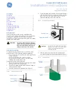
Align the bottom of the circuit board in the edge guide 
standoff and twist the standoff into place (

Figure 4

). Tighten 

the mounting screw (

Figure 2

).

Figure 4.

Installing the circuit board 

External mounting

This installation uses enclosure model NX-569 (600-1029-03). 
The module comes as a kit that is assembled in the field. Use the 
following installation guidelines:

• Allow at least 10 in. (25 cm) of clearance above the enclo-

sure for the antennas.

• Use the wire length guidelines in 

Table 1

.

• Install the module in its own plastic enclosure. It should not 

be installed inside the panel’s enclosure.

• Avoid mounting locations that expose the module to moisture.
• Avoid areas with excessive metal or electrical wiring 

including furnace and utility rooms. If unavoidable, mount 
on or near metal with the antenna extending above the 
metallic surfaces as shown in 

Figure 5

.

Figure 5.

Mounting on or near metal

Tools and supplies needed

To complete the installation, you will need the following tools 
and supplies:

• Screwdrivers;
• Drill with bits;
• Mounting screws and anchors (included); and
• 3-conductor, 22-gauge (0.65 mm) or larger, stranded wire.

Mounting

The module can be mounted on any interior wall (protected from 
the elements). To mount the module, do the following:
1.

Remove the module back plate from the packaging.

2.

Hold the base against the mounting surface and mark the 
two mounting holes and the wire access hole as shown in 

Figure 6

. Remember to leave at least 10 in. (25 cm) above 

the back plate for the antennas.

Note:  

The wire access hole is molded into the plastic so that 
you can access the wire, yet keep it hidden from the 
back plate.

Figure 6.

Back plate

3.

Drill holes and insert the appropriate anchors (included).

4.

Run a 3-conductor, 22 or 18 gauge (0.65 or 1.02 mm) 
stranded wire cable from the module wire access hole loca-
tion to the panel (

Figure 6

).

5.

Secure the back plate to the wall with the pan head screws 
provided.

6.

To assemble the antenna shrouds, attach the proper number 
of sections together, then attach the top cap.

7.

Install each antenna shroud on top of the back plate.

8.

Remove the transceiver circuit board from the antistatic bag.

Table 1.

Wire lengths

Wire gauge (shielded or unshielded)

Maximum wire length between 

module and panel

22 AWG (0.65 mm)

250 feet (76 m)

18 AWG (1.02 mm)

500 feet (152 m)

Circuit board

Edge guide standoff

Antenna shroud

Enclosure

Metal

Metal

CAUTION

You must be free of static electricity before 
handling circuit boards. Wear a grounding 
strap or touch a bare metal surface to 
discharge static electricity.

Antenna shroud locations

Mounting hole

Mounting hole

Wire access

Summary of Contents for NETWORX NX-548E

Page 1: ...nt the receiver do the following 1 Remove the appropriate knockouts on the top of the control panel enclosure for the antenna shrouds 2 Assemble the antenna shrouds and fit the black O rings to the bottom of each shroud 3 Insert the shrouds into the knockout holes Figure 1 Figure 1 Installing the antenna shrouds 4 Use the mounting screw provided to loosely install the edge guide standoff in the lo...

Page 2: ...or wall protected from the elements To mount the module do the following 1 Remove the module back plate from the packaging 2 Hold the base against the mounting surface and mark the two mounting holes and the wire access hole as shown in Figure 6 Remember to leave at least 10 in 25 cm above the back plate for the antennas Note The wire access hole is molded into the plastic so that you can access t...

Page 3: ...he bottom of the receiver Figure 8 may emit a dim glow but is not used as an indicator ON ECE ON ECE 1 2 3 4 1 2 3 4 Circuit board Wiring terminals LEDs DIP switches Top latches Bottom latch Antenna shrouds Back plate 12 to panel POS GND to panel COM DATA to panel DATA Green power LED Red data LED Red not used LED Table 2 DIP switch settings Module number 32 Module number 33 Module number 34 Modul...

Page 4: ...NX 8E This must be set before learning sensors For example if location 194 is set to 3 the first available location is 25 The total number of available locations depends on the zone limits for both the panel and receiver 6 Enter 0 to enter the sensor learning location On LED touchpads the Ready LED turns on and the Armed LED turns off 7 Enter the zone number 1 through 192 and press Three beeps fro...

Page 5: ...nel installation manual describes how keyfob functions 1 and 2 can be used to control relays outputs or X 10 devices Use the following guidelines when setting features 4 and 5 see Segment 1 in Table 5 on page 7 for 4 button keyfobs Feature 4 Input option 1 Turn on this feature to change the Light button to keyfob function 1 Feature 5 Input option 2 Turn on this feature to change the Star button to...

Page 6: ...start flashing 2 Enter the program code factory default is 9 7 1 3 On LED touchpads the service light flashes and the five function lights change from flashing to on steady 3 Enter the DIP switch setting module number and press On LED touchpads the Armed LED turns on indicating the control panel is waiting for a programming location entry 4 Enter the zone location number to be deleted and press On...

Page 7: ...artition 6 keyfob Partition 7 keyfob Partition 8 keyfob Zone _____ Assigned to module _____ RM HE P 1 Enable sensor 2 Supervised 3 Fire supervision 4 Input option 1 5 Input option 2 6 80 bit device 7 Input option 3 8 Not used Partition 1 keyfob Partition 2 keyfob Partition 3 keyfob Partition 4 keyfob Partition 5 keyfob Partition 6 keyfob Partition 7 keyfob Partition 8 keyfob Zone _____ Assigned to...

Page 8: ...ob Partition 6 keyfob Partition 7 keyfob Partition 8 keyfob Table 5 Programming settings continued Location Segment 1 Segment 2 Zone _____ Assigned to module _____ RM HE P 1 Enable sensor 2 Supervised 3 Fire supervision 4 Input option 1 5 Input option 2 6 80 bit device 7 Input option 3 8 Not used Partition 1 keyfob Partition 2 keyfob Partition 3 keyfob Partition 4 keyfob Partition 5 keyfob Partiti...

Page 9: ...ition 7 keyfob Partition 8 keyfob Table 5 Programming settings continued Location Segment 1 Segment 2 Zone _____ Assigned to module _____ RM HE P 1 Enable sensor 2 Supervised 3 Fire supervision 4 Input option 1 5 Input option 2 6 80 bit device 7 Input option 3 8 Not used Partition 1 keyfob Partition 2 keyfob Partition 3 keyfob Partition 4 keyfob Partition 5 keyfob Partition 6 keyfob Partition 7 ke...

Page 10: ...yfob Partition 8 keyfob Zone _____ Assigned to module _____ RM HE P 1 Enable sensor 2 Supervised 3 Fire supervision 4 Input option 1 5 Input option 2 6 80 bit device 7 Input option 3 8 Not used Partition 1 keyfob Partition 2 keyfob Partition 3 keyfob Partition 4 keyfob Partition 5 keyfob Partition 6 keyfob Partition 7 keyfob Partition 8 keyfob Zone _____ Assigned to module _____ RM HE P 1 Enable s...

Page 11: ...19 5 Standard Door Window Sensor White NX 651 60 362 11 319 5 Standard Door Window Sensor Brown NX 652 60 641 95 Long Life Door Window Sensor White NX 653 60 641 11 95 Long Life Door Window Sensor Brown NX 454 60 688 95 Micro Door Window Sensor White NX 455 60 688 11 95 Micro Door Window Sensor Brown NX 481 60 807 95R Indoor SAW PIR Motion Sensor NX 482 60 880 95 AP750W PIR Motion Sensor NX 488 60...

Page 12: ...liance could void the user s authority to operate the equipment Compatibility NX 4 NX 6 NX 8 NX 8E control panels Frequency 319 5 MHz Wireless range 1 000 feet 304 m Required power 12 0 VDC provided by panel Current draw 55 mA maximum Operating temperature 32 to 120 F 0 to 49 C Storage temperature 30 to 140 F 34 to 60 C Max relative humidity 85 noncondensing Dimensions 4 65 x 3 20 inches 11 8 x 8 ...

Reviews: