MDS
SDM9
Quick
Start
Guide
(x790
Mode)
2.
Install the antenna and feedline.
The antenna
used with the radio must be designed to operate in
the radio’s frequency band, and be mounted in a
location providing a clear path to the associated
station(s). At Remote sites, aim directional antennas
toward the Master Station. Low loss coaxial feedline
should be used and it should be kept as short as
possible.
3.
Connect the data equipment.
Connection may be
made to the COM port using Serial protocols (RS-
232/RS-485). RJ45 to DB9/DB25 adapters may be
required depending on physical data port connector
type used on the data telemetry device to be attached
as shown in Figure 3.
4.
Connect primary power to the Orbit Chassis.
Input power must within the ranges specified for the
power supply module installed in the Orbit chassis:
12VDC, 24VDC, 48VDC, 125VDC, or 90-264VAC.
These supplies all convert incoming power to +24V
for SDM9 Module operation.
5. Set the radio’s configuration.
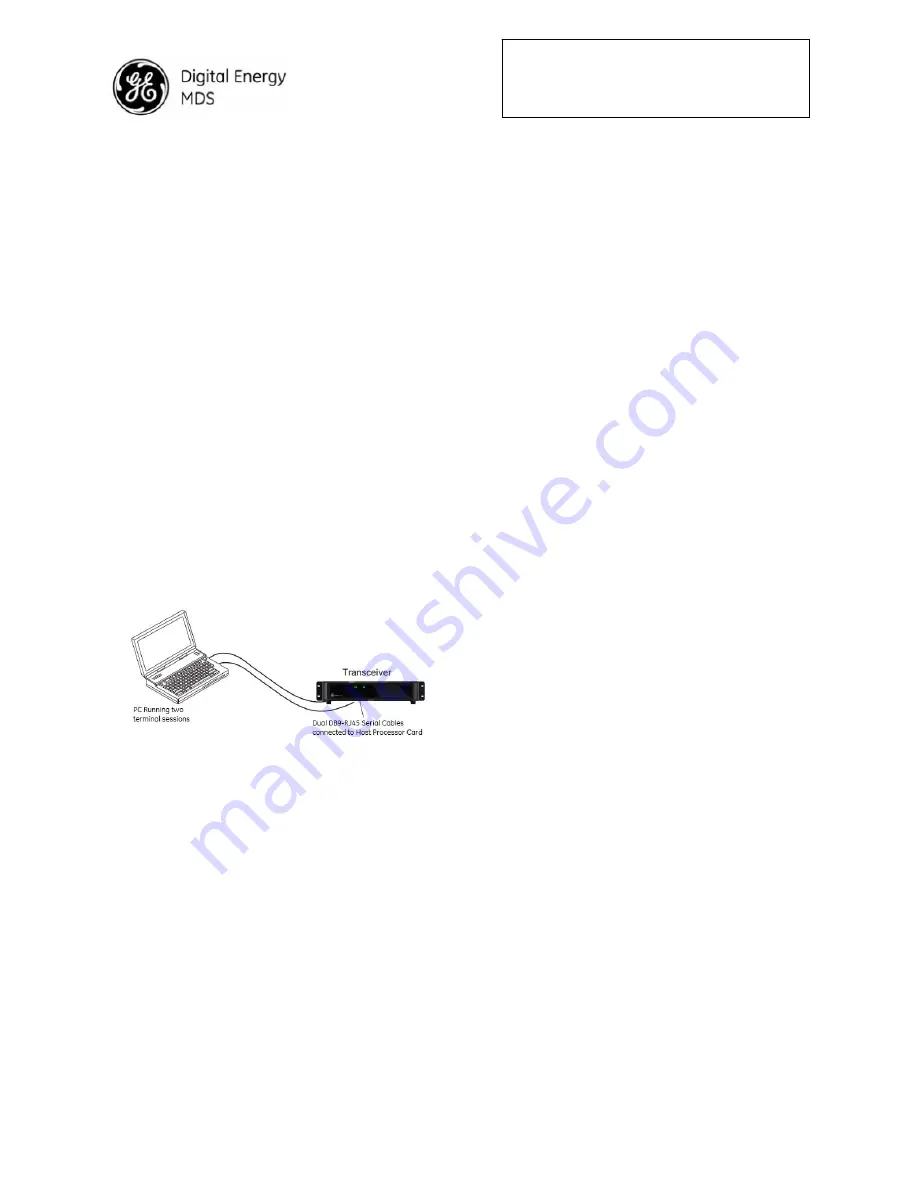
Connect a PC to
the radio’s COM1 and COM2 ports as shown in
Figure 4
. A straight-thru cable may be used for this
connection with an RJ45 to DB9 adapter.
NOTE:
Consult your System Administrator if you are unsure
of the settings required for your network.
Figure 4. Setup for PC Configuration
2.1.1 Software Configuration
There are two methods for communicating with the
radio for configuration and management:
Serial
(COM1, COM2 RJ45 connector) and
Telnet
(ETHERNET RJ-45 connector). Both present identical
functionality and use the same commands, but the
method to configure access is different for each.
NOTE: Transmitter and Receiver configuration are
handled through separate DSP devices, thus two
serial ports or two Telnet sessions will be required to
handle configuration of these two functions.
The focus here is on
Serial
access, but Telnet may be
used by following these additional points, which
replace Steps 1 and 2 below:
• For Telnet, connect to the radio with a PC
that is on the same IP network as the
transceiver. Launch a Telnet program, and
connect to the radio using its programmed IP
address for the Transmitter and Receiver.
• The default IP address of the Transmitter
configuration is 192.168.1.1. The default IP
address of the Receiver configuration is
192.168.1.2. If you do not know the IP
address of the radio, use the serial
configuration steps below to view the
address with the
IPCONFIG
command.
1. With a PC connected to the COM1 serial port,
launch a terminal program, such as HyperTerminal
(included withmost pre-Windows7
®
-based PCs) and
set the following parameters:
8 bits, no parity, one
stop bit (8N1), flow control disabled, VT100
emulation
. The COM port automatically finds the
connected baud rate (within 1200–115200 bps).
2. Press the ESCAPE key followed by a series of
ENTER keypresses (at 1/2 second intervals) until the
>
prompt appears. The radio is now ready to accept
commands.
3. Set/verify the
RX
(receive) and
TX
(transmit)
frequencies. To set the receive frequency, enter
RX
followed by the correct frequency in MHz
(
xxx.xxxxx
). Press ENTER . To set the transmit
frequency, enter
TX
followed by the correct frequency
in MHz (
xxx.xxxxx
). Press ENTER.
4. The factory default modem settings support 9600
bps transmission in a 12.5 kHz bandwidth channel.
Many other options are available. The current setting
may be viewed using the
MODEM
command. Use
MODEM [xxxx]
if changes are required.
When finished with the steps above, review the other
configuration options to determine if other settings are
required for your system.
Table 3
lists key software
commands for the radio.
2.2 Initial Checkout
In-service operation is completely automatic. The only
operator actions required are to apply DC power and
observe the LEDS for proper indications.
Table 1 on
the following page
summarizes the radio’s LED
functions.


