GE M
EDICAL
S
YSTEMS
D
IRECTION
2380207, R
EVISION
7
LOGIQ™5 PRO S
ERVICE
M
ANUAL
5-26
Section 5-7 - External I/O (Rear Panel)
Section 5-7
External I/O (Rear Panel)
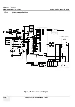
The External I/O is the interface between the scanner and all external items, located at the rear side of
the scanner.
Examples: InSite, TCP/IP network, Printer, etc.
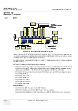
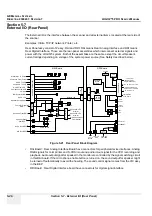
Rear Panel assy consist of 2 assy, RAI and RDI. RAI means Rear Analog Interface and RDI means
Rear Digital Interface. Those are the rear-panel assemblies which interconnect external signals and
power with the LOGIQ 5 system. Both of the assemblies are the same except the circuit breaker’s
current ratings depending on voltage of the system power source (See Safety described below).
•
RAI Board : Rear Analog Interface Board have connectors for peripheral device interfaces. Analog
RGB signals for color printer and S-VHS in/out and audio in/out signal for the VCR recording and
playback. Audio output signal for speaker in the monitor are controlled by the signal switching circuit
in this RAI board. If the microphone enable button is turned on, the sound output for speaker might
be turned off automatically to avoid the howling. The sound control signal comes from the VIC assy
in the BEP.
•
RDI Board : Rear Digital Interface board have connectors for digital signal interface
Figure 5-21 Rear Panel Block Diagram
R/G/B/Sync To Printer
Composite From Printer
S-VHS To VCR
Composite To VCR
S-VHS From VCR
Composite From VCR
VGA Out
BW Printer Shutter
Speaker Sound
from BEP
Audio In to BEP
VCR Audio In
VCR Audio Out
Speaker Sound Switch
MIC In to BEP
44P
DSUB
C
O
N
N
(J
56
)
8P
C
o
n
n
(J
58
)
Speaker Out To
Monitor
Speaker Out To
Monitor
Microphone Input
From Monitor
FOOT SW
Foot S/W Signal to
KBD
4P Conn
(J
57)
DC 5V, 12V
Isolated 12V
RAI Board
10
P
C
o
n
n
(J55)
10
P
Conn(
J
7
)
Ext VGA
4P
Con
n
(J
1
5
)
4P
Con
n
(J
5
1
)
DC DC
Convertor
VCR
Remote
Printer
Remote
Aux
SVC
ETHERNET
Phone Line
JPC
Conn(J6)
Shutter to Front BW
4P
Conn
(J
62)
2 USB from
Hub in KBD
JPC
Conn(J3)
Phone
Line to
Modem
LAN from
BEP
3Ports RS232
From PC2IP
JPC Control
(RackPower_En,
PeripheralPowe_En)
DC 5V from JPC to VIC
HDD Indicator/Power
Switch From VIC to KBD
To KBD
Conn(J4)
EEPROM
(System
S/N Infor)
IIC I/F from VIC
RDI Board
50
p C
o
nn
ec
to
r
Summary of Contents for LOGIQ 5 PRO
Page 2: ...GE MEDICAL SYSTEMS DIRECTION 2407381 REVISION 7 LOGIQ 5 PRO SERVICE MANUAL Page 1 2 ...
Page 3: ......
Page 7: ...GE MEDICAL SYSTEMS DIRECTION 2380207 REVISION 7 LOGIQ 5 PRO SERVICE MANUAL ii iii ...
Page 462: ...GE MEDICAL SYSTEMS DIRECTION 2380207 REVISION 7 LOGIQ 5 PRO SERVICE MANUAL A 4 Index INDEX ...

