


6
Kilsen KFP-CF Series Operation Manual
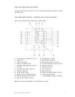
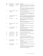
Item Control/LED
LED
colour
Description
10 General
Disable
button and LED
Yellow
Disables a zone, sounders, fire routing, or expansion
I/O module (when pressed with the corresponding
button).
A steady general Disable LED and the corresponding
zone, sounders, or fire routing Fault/Disable/Test
LED indicates a disablement.
11
General Test button
and LED
Yellow
Tests a zone, sounders, or fire routing (when pressed
with the corresponding button).
A steady general Test LED and the corresponding
zone, sounders, or fire routing Fault/Disable/Test
LED indicates a test.
12
Numeric keypad and
Enter button
N/A
Used to enter the access level 2 password. The Enter
button is also used to disable expansion I/O modules
(when pressed with the general Disable button).
13
Reset button
Yellow
Resets the control panel and clears all current
system events (except expansion I/O module fault
communication).
A steady LED indicates that access level 2 is active
(see “Access levels” on page 10).
14 Panel
Silence
button
and LED
Yellow
Silences the internal buzzer and acknowledges all
current events.
A steady LED indicates that all current events were
acknowledged.
15 Sounder
Start/Stop
button and LED
Red
Stops (silences) all active sounders. Pressing the
button again restarts them.
A flashing LED indicates that sounders activate
when a configured delay elapses. A steady LED
indicates that the sounders are active (sounding).
16
System Fault LED
Yellow
Indicates a control panel CPU failure.
17
Out of Service LED
Yellow
Indicates that the control panel is not operational.
18
Earth Fault LED
Yellow
Indicates an earth fault.
19
Supply Fault LED
Yellow
Indicates a fault with the power supply.
A flashing LED indicates a battery or battery fuse
fault. A steady LED indicates a mains or mains fuse
fault.
20 Fire
Routing
Delay
button and LED
Yellow
Enables or disables a previously configured fire
routing delay.
A steady LED indicates that a fire routing delay is
configured and enabled.
21
Fire Routing Start
button and LED
Red
Cancels a previously configured delay and activates
fire routing.
A flashing LED indicates that fire routing activates
when the configured delay elapses. A steady LED
indicates that fire routing is active.


