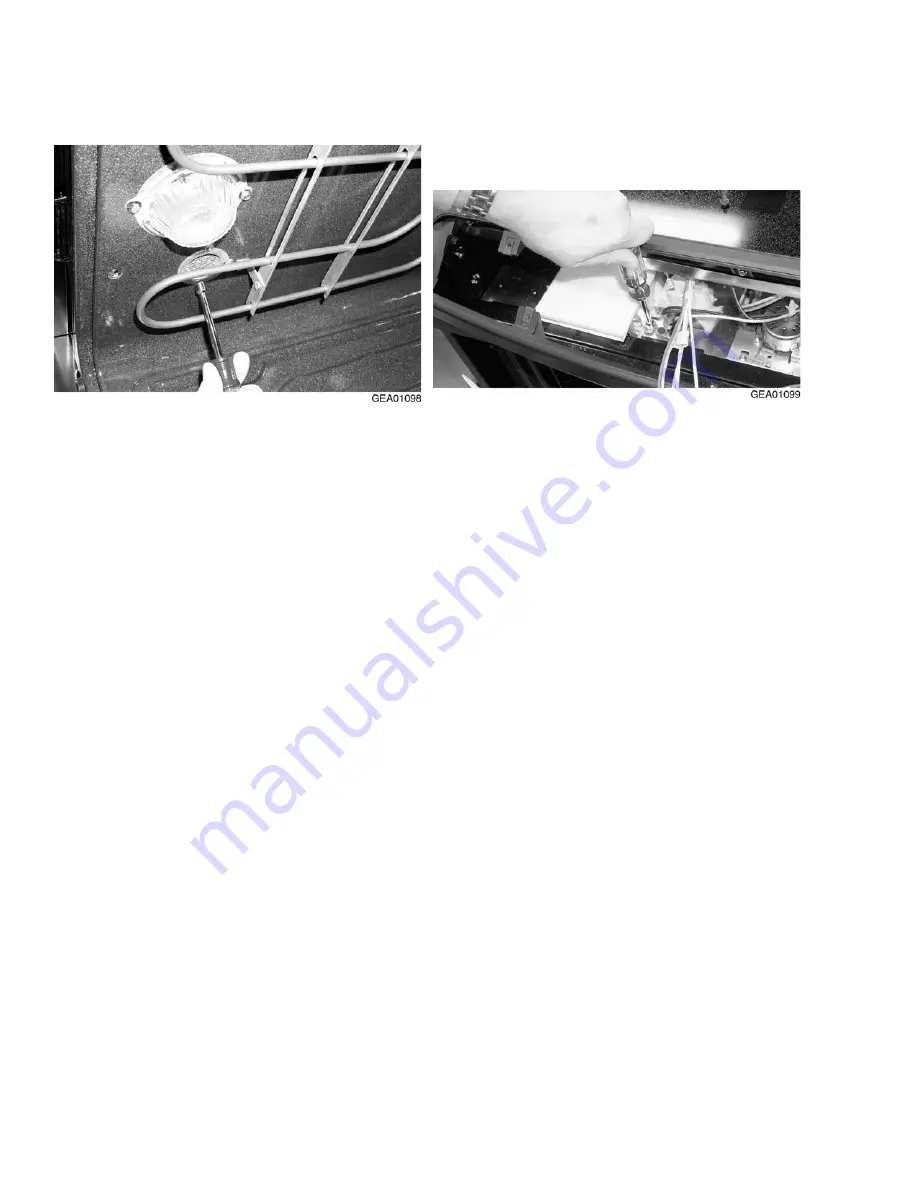
GE JS966 Technical Service Manual Download Page 38

36

Oven Vent Removal

1.   Remove the 2 screws that secure the vent

tube to the top of the oven. Remove the tube.

2.   Remove the control panel (see procedure).

3.   Remove 1 screw from the vent cover and pull

the vent cover tabs out of the slots in the
cabinet. Remove the vent cover.

www.Appliantology.org

Summary of Contents for JS966

Page 1: ...ervice Training TECHNICAL SERVICE GUIDE PUB 30 in Electric Drop In Slide In Range Drop In JD966 JDP46 31 9074 06 01 GE Consumer Home Services Training Slide In JS966 JSP56 JSP46 w w w A p p l i a n t...

Page 2: ...nnect power before servicing this prod uct If electrical power is required for diagnosis or test purposes disconnect the power immediately after performing the necessary checks RECONNECT ALL GROUNDING...

Page 3: ...on 3 Specifications and Nomenclature5 21 Warranty Information 22 Features and Controls 23 Mechanical Disassembly 29 DiagnosticsX 37 Component and Connector Locator Views 41 Schematics and Strip Circui...

Page 4: ...zone for very low heat cook ing preparing sauces and keeping food warm and ready to enjoy The convection baking and roasting feature provides even cooking and supe rior baking every time It s easy to...

Page 5: ...Clearances Drop In Range 5 Slide In Range 6 Standard Installation Preparation 7 Electrical Connections Drop In Range 8 Slide In Range 11 Anti Tip Bracket Installation Drop In Range 12 Slide In Range...

Page 6: ...HU RU IXVH KDYLQJ DPSHUDJH DV VSHFLILHG RQ WKH UDWLQJ SODWH 7KH UDWLQJ SODWH LV ORFDWHG DERYH WKH VWRUDJH GUDZHU RQ WKH RYHQ IUDPH H UHFRPPHQG RX KDYH WKH HOHFWULFDO ZLULQJ DQG KRRNXS RI RXU UDQJH FRQ...

Page 7: ...5 Cutout Dimensions and Required Clearances Drop In Range w w w A p p l i a n t o l o g y o r g...

Page 8: ...8 5 1 2 19 5 1 2 29 15 16 MIN 30 1 16 MAX 23 3 16 7 Acceptable Electrical Outlet Area 30 Min 30 Min from cooking surface to bottom of overhead cabinets Shave Raised Edge To Clear 31 1 8 Wide Control...

Page 9: ...30 1 16 Smooth Cut Wall 9 16 Min Flat 1 4 Min Flat 9 16 Min Flat 1 4 R FLAT AREA Slide In Drop In Grounding Specifications Ground Path Resistance 0 10 Max Insulation Resistance 250K Min 36 in The Sta...

Page 10: ...zard or fire Use only connectors designed for joining copper to aluminum and follow the manufacturer s recommended procedure closely Feed wires and conduit through the open hole and snap the conduit f...

Page 11: ...H QHXWUDO KLWH OHDG IURP WKH FULPS 5H VWULS WKH QHXWUDO ZKLWH OHDG WR H SRVH WKH SURSHU OHQJWK RI FRQGXFWRU DQG FRQQHFW LW WR WKH ZKLWH RU JUD EUDQFK FLUFXLW QHXWUDO LQ DFFRUGDQFH ZLWK ORFDO FRGH XVLQ...

Page 12: ...KH SURSHU VL H LV REWDLQHG 127 72 75 1 7KH SRZHU OHDGV VXSSOLHG ZLWK WKLV DSSOLDQFH DUH 8 UHFRJQL HG IRU FRQQHFWLRQ WR ODUJHU JDXJH KRXVHKROG ZLULQJ 7KH LQVXODWLRQ RI WKHVH OHDGV LV UDWHG DW WHPSHUDWX...

Page 13: ...re the wires do not become pinched between wire cover and housing 50 Amp 4 Wire C4a Follow instructions below if your cord is 4 wire C4b Remove the screws on the terminal block Do not remove terminal...

Page 14: ...W LQ SRVLWLRQ Wire Cover Wall Stud Anti Tip Bracket Bottom of Countertop To Engage Bracket By 1 2 Min Glass Maintop Interior Wall ANTI TIP INSTALLATIONS Bottom of Countertop Countertop Thickness Min 1...

Page 15: ...I WKH UDQJH RQ FRXQWHUWRS COUNTER TOP CABINET RANGE LIFT SLIDE RANGE ON COUNTER TOP Countertop Make sure the edge of the countertop fits flush against the end of the Front Control Panel QVWDOO 6WRS 6F...

Page 16: ...HG LQ WKH QRWFK RQ WKH VLGHV RI WKH UDQJH DQG QRW WRXFK WKH WRS RI WKH QRWFK ZKHQ WKH UDQJH LV IXOO VHDWHG RQ WKH FRXQWHUWRS I WKH VFUHZV GR QRW PHHW WKH UHTXLUHPHQWV PRYH WKH VFUHZV WR D SRVLWLRQ WKD...

Page 17: ...DEOH DQG QRW WLS RQFH WKH DQWL WLS EUDFNHW LV HQJDJHG 0DNH VXUH ERWK KLQJHV DUH LQ WKH EURLO VWRS SRVLWLRQ 5HSODFH WKH 2YHQ RRU UDVS WKH GRRU RQ ERWK VLGHV LIW WKH GRRU RYHU WKH KLQJHV OLQLQJ XS WKH K...

Page 18: ...and Wall b Drill a 1 8 pilot hole through the pre marked areas Note the angle of the wall screw in Fig 2 c Mount the Anti Tip bracket with the four screws provided Locating The Bracket a Decide whethe...

Page 19: ...overhang comes to rest on the counter top E6 Then carefully screw in the front two leveling legs similar to E5 until the glass overhang touches the countertop Plug range cord into receptacle Locate t...

Page 20: ...help lifting the door high enough to slide it down onto the hinges Do not lift the door by the handle Replacing the Oven Door Place the drawer rail on the guides Replacing the Storage Drawer E14 Push...

Page 21: ...WHO 5HFKHFN WKH UDQJH ZLULQJ FRQQHFWLRQV I D FKDQJH LV PDGH WR FRQQHFWLRQ UHWHVW DJDLQ I QR FKDQJH LV UHTXLUHG KDYH EXLOGLQJ ZLULQJ FKHFNHG IRU SURSHU FRQQHFWLRQ DQG YROWDJH W LV UHFRPPHQGHG WKDW WKH...

Page 22: ...20 Notes w w w A p p l i a n t o l o g y o r g...

Page 23: ...ears Example T 1974 T 1986 T 1998 J D 9 6 6 B Product J GE Cooking Product Configuration D Drop In S Slide In Feature Pack Designates features the higher the number the more features Color B Black The...

Page 24: ...s warranty gives you specific legal rights and you may also have other rights which vary from state to state To know what your legal rights are consult your local or state consumer affairs office or y...

Page 25: ...ranges feature a ceramic glass cooking surface over an electric radiant heating element The oven touch controls on the glass cotrol panel surface take the place of control knobs Appearance Defects Scr...

Page 26: ...0 0 5 1 t n e m e l E l a u D n i 9 0 4 2 0 0 5 2 t n e m e l E e g d i r B 0 4 2 0 0 6 2 n i 6 0 2 1 0 2 1 Models JDP46 and JSP46 Models JSP56 JS966 and JD966 6 in 1500 W 6 in 120 W 9 in Dual 2500 W...

Page 27: ...en operation and a power outage occurred the clock and all programmed functions must be reset The time of day will flash in the display when there has been a power outage CLOCK Pad Touch this pad befo...

Page 28: ...unt of time you want your food to cook The oven will shut off when the cooking time has run out DELAY START Pad Use along with COOKING TIME or SELF CLEAN pads to set the oven to start and stop automat...

Page 29: ...ned White Patterned Bisque Patterned Bisque Glass ceramic cooktop Patterned Black Patterned Black White Porc Enam White or Almond White or Almond Lift up overhanging cooktop Black Porc Enam Porc Enam...

Page 30: ...thermometer Heating element ON indicator light Interior oven light Halogen Stainless White White White White White Bisque Bisque Bisque Almond Black Storage drawer Black Black Black Black CM CM Broil...

Page 31: ...or Removal 31 Range Removal 31 Convection Fan Motor Removal 32 Control Panel Removal 32 Light and Receptacle Removal 34 Meat Probe Outlet Removal 34 Thermal Circuit Breaker Removal 34 Door Latching Mo...

Page 32: ...n fan guard to the rear wall of the oven and remove the fan guard GEA01072 Screws Screws Screws Screws Screws Convection Element Convection Element 2 Remove 1 screw from the mounting bracket on the bo...

Page 33: ...oven door see procedure 2 Remove the storage drawer 3 Unplug the range through the storage drawer opening Caution Take the necessary precautions to protect the floor from damage that could be caused...

Page 34: ...ft GEA01078 Screws Screws Screws 5 Remove the 6 screws that secure the service cover to the rear of the range and remove the cover 6 Remove the wiring harness connectors from the motor terminals 7 Rem...

Page 35: ...under the knobs GEA01083 Touch Board Touch Board Harness Harness Connector Harness Connector Caution Lift the panel faceplate enough to access the wire harness connected to the touch board 2 Remove t...

Page 36: ...4 Lower the outlet pull the wiring through the access hole and remove Thermal Circuit Breaker Removal 1 Place the control panel in the service position see Control Panel Removal procedure 2 Disconnec...

Page 37: ...inals m t e r m i n a l s GEA01094 Screws Screws Screws Mounting Mounting Clips Mounting Clips 4 Mark the numbers nearest the mounting clips for reassembly of the new heating element and remove the sc...

Page 38: ...e the vent tube to the top of the oven Remove the tube 2 Remove the control panel see procedure 3 Remove 1 screw from the vent cover and pull the vent cover tabs out of the slots in the cabinet Remove...

Page 39: ...Table of Contents Failure Codes 38 Key Panel Test 39 Oven Light Test 39 Control Voltages 39 Door Lock Thermostat 40 Fan Thermostat 40 Convection Fan 40 Motorized Door Lock 40 w w w A p p l i a n t o...

Page 40: ...r a e l c d e k c o l b r o d e l l a t s n a f g n i l o o C z t i n u f o r a e r o t w o l f r i A z s r o t c e n n o c s d a e l r o s n e s n e v o n i e c n a t s i s e r h g i H 3 F r o s n e...

Page 41: ...ng voltages and show unstable nonzero voltage when measured with a voltmeter Oven Light Test If the oven light is not working make the following checks z z z z z Check oven light bulb z z z z z Light...

Page 42: ...uit that supplies the voltage to the lock motor Note The display of the control will flash LOCK DOOR if the door switch is in the C to NC position door open The words LOCK DOOR will flash in the displ...

Page 43: ...15 Pin Cooktop Connector Right Front Surface Switch Right Front Surface Switch Left Front Surface Switch Left Front Surface Switch ON Lights ON Lights Left Rear Surface Switch Left Rear Surface Switc...

Page 44: ...Unit Surface Element Hot Surface Light Switches Light Switches Hot Surface Light Switches Cooktop Connector Connector Cooktop Connector Bridge Element Bridge Element Bridge Element Warming Zone Warmi...

Page 45: ...or Connector Motor Lock Motor Lock Oven Element Connectors Oven Element Connectors Power Connector Power Connector Oven Door Switch Oven Door Switch Meat Probe Meat Probe Meat Probe Connector Meat Pro...

Page 46: ...44 JD966 and JS966 Convection Fan Motor Convection Fan Motor GEA01066 w w w A p p l i a n t o l o g y o r g...

Page 47: ...tch Right Rear Surface Switch Right Front Surface Switch Right Front Surface Switch Left Rear Surface Switch Left Rear Surface Switch Left Front Surface Switch Left Front Surface Switch Electronic Ove...

Page 48: ...m 48 Strip Circuits Right Rear Surface Switch 49 Left Rear Surface Switch 49 Left Front and Right Front Surface Switches 49 Bake and Broil Units 49 Convection Bake 49 Convection Roast 49 Motorized Doo...

Page 49: ...all wires prior to disconnection when servicing the controls Wiring errors can cause improper and dangerous operation Verify proper operation after servicing GEA01060 Schematic w w w A p p l i a n t...

Page 50: ...48 GEA01061 Wiring Diagram w w w A p p l i a n t o l o g y o r g...

Page 51: ...ke and broil units operate sequentially during first preheat cycle 1 second dead time between bake and broil units while calling for heat in clean L2 RED L1 BLACK L1 BROIL L2 RED BROIL RELAY 2700W 16...

Page 52: ...OTOR DOOR SWITCH DOOR LOCKING OR UNLOCKING ALL OTHER MODES WITH DOOR CLOSED COM MDL COM MDL GEA01058 Motorized Door Lock Cooling Fan Oven Light Strip Circuits LIMIT SW CLOSE 138 F OPEN 106 F GEA01102...

Reviews: