background image

P R O D U C T   A P P L I C A T I O N   N O T E

Videofied Upgrade - GE Interlogix

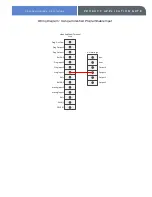
Wiring Diagram - Using a Videofied Programmable Input

Prog. Out. Com

Prog Output 2

Prog Output 1

Ref GND

Prog Input 3

Prog Input 2

Prog Input 1

Ref +

Ref GND

Arming Input 2

Arming Input 1

Ref +

PWR (-)

PWR (+)

Videofied Panel Terminal 

Strip

GE Interlogix

Output 1

Output 2

Output 3

Output 4

Aux +

Aux -

Summary of Contents for Interlogix

Page 1: ...Videofied Upgrade With GE Interlogix ...

Page 2: ...OR CODE enter you installer code YES www videofied com Using the RIGHT ARROW go to CONFIGURATION and press YES CONFIGURATION GENERAL PARAMETERS XTENDER Press YES on GENERAL PARAMETERS Using the RIGHT ARROW go to XTENDER and press YES ARMING OPTION FROM THE HOST With the display showing ARMING OPTION press YES and use the arrow keys to change it to FROM THE HOST and press YES ENTRY DELAY 0 RIGHT AR...

Page 3: ...on Videofied Upgrade to GE Interlogix series control panels requires configuration of one output function for arming and disarming ARM FUNCTION Enter Address of 0 zero to configure output number 4 or go to next unprogrammed output option Enter Location 50 Enter 21 in segment 1 21 armed state Enter 2 in Segment 2 Refer to control panel manual for table of conditions Press exit button twice to exit ...

Page 4: ...Relay NO C POS NEG Prog Out Com Prog Output 2 Prog Output 1 Ref GND Prog Input 3 Prog Input 2 Prog Input 1 Ref Ref GND Arming Input 2 Arming Input 1 Ref PWR PWR Videofied Panel Terminal Strip GE Interlogix Output 1 Output 2 Output 3 Output 4 Aux Aux 4 Terminal SPDT Relay NO C POS NEG 12v Power Source Note Wiring will be different depending on if the Videofied control panel is being powered by a 12...

Page 5: ...YES on the PROGRAMMABLE INPUT 1 TRANSMISSION Press YES on TRANSMISSION and choose the desired option using the arrow keys and YES Enable Input is listening all the time Disable Input is disabled Only If Armed Input is listening only when system is armed ALARM MODE RIGHT ARROW to ALARM MODE and press YES Use the arrow keys to choose the desired option followed by YES Alarm Event is transmitted Alar...

Page 6: ...is gives you the option to capture a video from a MotionViewer when the input is triggered Use the arrow keys to choose a installed MotionViewer from the list and press YES Press and hold the ESC NO key for 5 seconds to go back to the main screen STEP 2 CONFIGURE GE Interlogix OUTPUT Enter Installer Programming Mode Enter 8 then installer code Enter Address of 0 zero To configure output number 3 o...

Page 7: ...ring Diagram Using a Videofied Programmable Input Prog Out Com Prog Output 2 Prog Output 1 Ref GND Prog Input 3 Prog Input 2 Prog Input 1 Ref Ref GND Arming Input 2 Arming Input 1 Ref PWR PWR Videofied Panel Terminal Strip GE Interlogix Output 1 Output 2 Output 3 Output 4 Aux Aux ...

Page 8: ...e GE Interlogix 3 E X A M P L E A P P L I C A T I O N F O R I N P U T OBJECTIVE Configure any burglary condition on the GE Interlogix control panel to create a burglary condition on the Videofied panel and to report an intrusion signal to the central station with a video from MotionViewer 1 Videofied Programmable Input Configuration TRANSMISSION ENABLED ALARM MODE ALARM Event only is transmitted I...

Reviews: