


NOTE
Motion controls installed in remote location from the table shall be installed at a location
where all the positioner axis are visible by the operator.
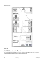
Refer to Illustrations in
2.2.2.1 Patient Room Layout on page 72
to see possible exam / control rooms
layouts.
2.3 Room Structural Requirements
2.3.1 Floor Requirements
General Vascular GE Healthcare Policy
GE Healthcare’s Customer is responsible for the structural analysis and mounting of the base plates.
If GE Healthcare is forced to mount the base plate, the Local Customer Team must hire a structural
engineer to design and approve the mounting method and provide GE Healthcare with an
engineering report.
The floor level cannot exceed a general levelness of 5 mm (0.2 in) for any 2 meters (79 in).
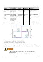
NOTICE
The floor slabs on which the equipment is to be installed must have a levelness
of 1 mm (0.04 in) per meter (40 in). Position of baseplates and table basement
depends on the type of installation. The three types of installation are given in
.
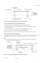
Figure 2-43
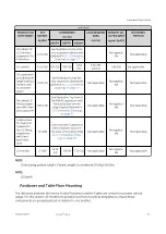
The preferred installation method for the Innova Frontal and Lateral Positioner or the Omega tables is
through-bolting. The through-bolting method can be used in all seismic zones. If through-bolting cannot
be used, use provided floor anchors instead.
Equipment Requirements
86
Innova
TM
IGS 6
5750182-1EN 3
Summary of Contents for Innova IGS 6
Page 9: ...Page intentionally left blank...
Page 57: ...Figure 2 11 Omega V Table dimensions Equipment Requirements 46 InnovaTM IGS 6 5750182 1EN 3...
Page 61: ...Figure 2 14 Gas box outlets Omega Table Equipment Requirements 50 InnovaTM IGS 6 5750182 1EN 3...
Page 69: ...Figure 2 22 C2 Cabinet dimensions Equipment Requirements 58 InnovaTM IGS 6 5750182 1EN 3...
Page 147: ...Page intentionally left blank Environmental Requirements 136 InnovaTM IGS 6 5750182 1EN 3...
Page 158: ...Figure 5 6 PDB Schematic CE 1 2 Electrical Requirements 5750182 1EN 3 InnovaTM IGS 6 147...
Page 159: ...Figure 5 7 PDB Schematic CE 2 2 Electrical Requirements 148 InnovaTM IGS 6 5750182 1EN 3...
Page 161: ...Figure 5 9 PDB Schematic UL 1 2 Electrical Requirements 150 InnovaTM IGS 6 5750182 1EN 3...
Page 194: ...InnovaTM IGS 6...


