Looking for the GE IBCG51M Instructions Manual? Look no further! Download your free manual from manualshive.com and get all the details you need to operate and maintain your GE IBCG51M product effortlessly.
6EK-49822
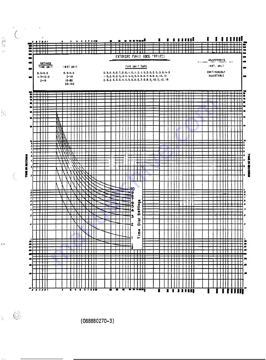
MULTIPLES OF RELAY TAP SETTING
Fig. 16
Time-current Characterisitc of Very
Inverse Time Overcurrent Unit
39
Page 1: ...INSTRUCTIONS 6EK 498sm Supersedes GEK 49822 GROUND DIRECTIONAL OVERCURRENT RELAYS TYPES IBCG51M IBC4 Hi UA IBCG53M IBCG53M YlA IBCG54M IBCG77M IBCG78M T i I GENERAL ELECTRIC...
Page 2: ...TEST 14 TIME OVERCURRENT UNIT 15 CURRENT SETTING 15 TIME SETTING 16 PICKUP TEST 16 TIME TEST 16 PAGE DIRECTIONAL UNIT 17 CURRENT POLARIZATION 17 POTENTIAL POLARIZATION 17 INSTANTANEOUS UNIT 17 INSTALL...
Page 3: ...nected in series with the contacts of the time overcurrent unit so that it will pick up whenever the time overcurrent unit operates The contacts of the seal in unit are connected in parallel with the...
Page 4: ...should be used on systems where the fault current flowing through a given relay is influenced largely by the system generating capacity at the time of the fault Very inverse time and extremely invers...
Page 5: ...he maximum external fault current The effects of transient overreach as illustrated in Fig 19 should also be taken into account in determining the setting RATINGS The IBCG relays described in this ins...
Page 6: ...51M IBCGSlM YlA Rating 1 6 1 8 2 0 2 1 2 3 2 7 3 0 3 5 4 0 4 5 5 0 IBCG52M Amps IBCG53M IBCG53M YlA 4 0 4 5 5 5 5 5 6 0 7 0 7 5 9 0 10 0 11 0 13 0 IBCG54M IBCG78M 3 5 3 7 4 0 4 5 5 0 5 5 6 0 7 0 8 0 9...
Page 7: ...ped for operation on either one of two ranges H or L Selection of the high or low range is determined by the position of leads T and E at terminal 6 See Table 6 and the applicable internal connections...
Page 8: ...an auxiliary relay which in turn energizes the trip coil or coils On such an application it may be necessary to connect a loading resistor in parallel with the auxiliary relay coil to allow enough cur...
Page 9: ...operate repeatedly within one or two percent of the same time The time current characteristic of the Hi Seismic instantaneous unit is shown by l Fig 18 and its transient overreach characteristic is s...
Page 10: ...pickup current tap rating varies inversely approximately as the square of the current rating Example for the Type IBCGSlM relay 0 5 4 amperes the impedance of the 0 5 ampere tap is 22 ohms The im eda...
Page 11: ...the time overcurrent unit are shown in Fig 20 They are of the low gradient type specially constructed to minimize the effects of vibration Both the stationary and moving contact brushes are made of lo...
Page 12: ...it operates it raises a target into view which latches up and remains exposed until manually released by pressing the button located at the lower left corner of the cover INSTANTANEOUS UNIT The IOC un...
Page 13: ...the proper location s as shown by the internal connec tions diagrmas Figs 5 to 9 inclusive and that the main brush is properly formed t0 contact the shorting bar MECHANICAL INSPECTION Top Unit TOC 1 T...
Page 14: ...omagnets such as time overcurrent relays is affected by non sinusoidal waveforms TARGET AND SEAL IN UNIT I The target and seal in unit has an operating coil tapped at 0 2 and 2 0 amperes When used wit...
Page 15: ...inding 2 Remove the tap screw and place it in the tap marked for the desired pickup current 3 Replace the connecting plug _ The minimum current required to rotate the disk slowly and to close the cont...
Page 16: ...is set on 10 the disk must travel the maximum amount to close the contacts and therefore this setting gives the maximum time setting The primary adjustment for the time of operation of the unit is ma...
Page 17: ...the instantaneous unit to a desired pickup loosen the locknut and adjust the core Turning the core clockwise decreases the pickup turning the core counterclockwise increases the pickup Bring up the c...
Page 18: ...ned Refer to Fig 21 OPERATION Before the relay is put into service it should be given a check to determine that I factory adjustments have not been disturbed The time dial will be set at zero before t...
Page 19: ...t progrma be followed It is recognized that the interval between periodic checks will vary depending upon environment type of relay and the user s experience with periodic testing Until the user has a...
Page 20: ...djusted so that the disk shaft has about1 64 inch end play Contact Adjustment The contacts should have about l 32 inch wipe That is the stationary contact tip should be deflected about l 32 inch when...
Page 21: ...epressing the spring mounted jewel until the cup strikes the iron The shaft should move about l 16 inch _ Cup and Stator 1 Should it be necessary to remove the cup type rotor fron the directional unit...
Page 22: ...ias Torque Adjustment Connect the current operating and current polarizing coils in series by connecting a jumper across terminals 5 and 8 Apply current to terminals 4 and 7 and adjust the directional...
Page 23: ...fine silver contacts a flexible burnishing tool should be used This consists of a flexible strip of metal with an etched roughened surface resembling in effect a superfine file The polishing action is...
Page 24: ...GEK 49822 Fig 1 8043458 Type IBCGHM YlA or the 18CG53M in its Case Front View Indicates Revision 24 YlA Relay...
Page 25: ...iT LTOC DISK LOCKING S C R E W PICKUP ADJUSTING RING 4 LO GRADIENT C O N T A C T DIRECTIONAL CUP UNIT TOC MOVING CONTACT Indicates Revision 25 LOCKING SCREW CLUTCH ADJUSTING t S C R E W CONTACT STOP S...
Page 26: ...1 C THYRITE DISK GEK 49822 l Fig 3 8043460 Type IBCG51M YlA or the IBCG53M YlA Relay Removed from Case Rear View Indicates Revision 26...
Page 27: ...GEK 49822 C T O C RESISTOR THYRITE DISK i Fig 4 8043461 Type IBCG77M or IBCG78M Relay Removed from Case Rear View Indicates Revision 27...
Page 28: ...TOC TRPN 54 LA 4 a 5 4 SI SEAL IN UNIT TOC TIME OVERCURRENT UNIT 3 DIRECTIONAL UNIT CU RR POL THY RITE c2 P D PC l POT 1 POL I V 1 IO k SHORT FINGER Fig 5 0269A3061 0 Internal Connections for IBCGSlM...
Page 29: ...TANTANEOUS UNIT CI c c TOC TRANSF b T T CURR POL THYRITE 6 8 P3 P4 II POT POL t SHGRT FINGER 51 SEAL IN UNIT TOC TIME OVERCUkRENT UNIT 0 DIRECTIC NAL UNIT Fig 6 02691 3062 0 Internal Connections for I...
Page 30: ...1 NIT TOC TlhlF OVERCl WKENT 1NlT C DIRECTICN AL JNIY c 4 C i PFft rot I 6 I F G SHORT FINGER D POT l FOL Fig 7 02X 9194 0 Internal Connections Diagram for the IBCG52M A and the IBCG54M A Relays Front...
Page 31: ...TOC Sl L I 51 L I SI SEAL IN UNIT TOC TIME OVERCUKRENT UNIT D DIRECTIONAL UNIT EL XRR FOL 0 F F4 cz 1 1 I 15 L 1IO 0 POT FOL rC SHORT FINGER Fig 8 026gA3063 0 Internal Connections for IBCG77M Relay Fr...
Page 32: ...u 49822 SI SEAL IN UNIT TOC TIME OVERCURRENT UNIT C DIRECTIONAL UNIT AT FQL B O g SHORT FINGER l Fig 9 0127A9424 0 Internal Connections Diagram for the IBCG7BM A Relay Front View Indicates Revision 32...
Page 33: ...TW POIAFtIEATION I S NOT ESEZI 3 21 CCh ECT C M R IFCUNRENTPOIABIZATIO lIS 8 NOT EED DO NOT CONNECT MsmD7 8 LXih 67NJBCC51M 53MAND 77M TOCTIMEOVhC UNIT D DIRECTIONAL UNIT T SLTARCETANDSFU IN OHIT Fig...
Page 34: ...T ATOD AND BTDC IF POTENTIAL 67N POLARIZATION IS NOT USED CONNECT CTOD SEE NOTE 2 7 7 2 IF CURRENT POLARHATION IS NOT USED r DONOT CONNECT TO STUDS 7ANDB 67N IBCG5IWlYIA IBCG53MA YIA D DIRECTIONAL UNI...
Page 35: ...POLBRIZATION IS NUT USED DO NOT CONMCT TO STUDS 7 S LECEK9 67W IF3BcG52M 53t 4 78M IoClXSTAKTA EDUS OVERCUFRmT UNIT TOCTMEOVKRCURRWT UNIT nDlRECTIONAL UNlT TASLTARXT SFAL IF UNIT I Fig 12 275A4559 0 E...
Page 36: ...L i i I I I I I i I I I I 0 L...
Page 37: ...6EK 49822 Fig 14 0376A0934 0 Time Characteristic of Dual Polarized Directional Unit of Type IBCG Relay 37...
Page 38: ...W 49822 Fig 15 088880269 3 Time current Characteristic of Inverse Time Overcurrent Unit 38...
Page 39: ...6EK 49822 j I I I 9 I 1 I rirll MULTIPLES OF RELAY TAP SETTING Fig 16 0888B0270 3 Time current Characterisitc of Very Inverse Time Overcurrent Unit 39...
Page 40: ...6u 49822 _ M U L T I P L E S O F R E L A Y T A P SETTING Fig 17 0888802746 Time current Characteristic of Extremely Inverse Time Overcurrent Unit 40...
Page 41: ..._ _ _ c ltKOJS NI 3Wlldll i3ld ltKOJS NI 3Wlldll i3ld Fig 18 0208A8695 1 Time current Characteristics of the Hi Seismic Instantaneous Unit 41...
Page 42: ...6EK 49822 _ I 1 I j cl 7 i y 9 I Z _ _ 3 t8 I I i I i 8 I Fig 19 0208A8694 2 Transient Overreach Characteristics of the Hi Seismic Instantaneous Unit 42...
Page 43: ...y Contact Support c Contact Tip L Mounting Screw H Stationary Contact Brush Retainer M Locknuts 0 Moving Contact Arm E Moving Contact Brush F Button Contact Tip G Moving Contact Brush Retainer Fig 20...
Page 44: ...6EK49822 2 5 a W I z al u Z I 5 ii Fig 21 8025039 Cross Section of Drawout Case Showing Position of Auxiliary Brush 44...
Page 45: ...GEK 49822 L I I A Or GLl FR a L Fig 22 D195A9179 0 Test Connections for Checking Pickup of TDC Unit 45...
Page 46: ...6EK 49822 C A 12ov l 1DTMER RATED 1 ___q5 O wfoP ADJ IIES C m 1 L1 1 Fig 23 01951 9180 0 Test Connections for Checking Operating Time of TDC Unit 46...
Page 47: ...m 49822 I 2 4 6 8 10 TTPE XLA13 TEST PLUG I Fig 24 0195A9181 1 Test Connections for Checking Pickup of Directional Unit using Current Polarization 47...
Page 48: ...I 6EK49822 Fig 25 0195A9182 0 Test Connections for Checking Pickup of Directional Unit using Potential Polarization 48...
Page 49: ...406 I A s P ANEL 1 9 9 mLES VIEW SHOWING ASSEMBLY OF HARD PANEL DRLLIN6 FOR WARE F X SURFACE SEMI FLUSH MOUNTING MTG ON STEEL PANE L S PANEL OffILLING FOR FRONT VIEW SURFACE MOUNTING FRONT VIEW Fig 2...