


General theory of operation
Invenia ABUS 2.0 – System Setup and Basic Service Manual
5-13
4700-0043-00 Rev. 4
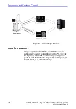
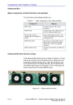
SSD (Solid State Drive)
The PC Box has one Solid State Drive mounted within the
Motherboard Compartment and the drive is accessible without
dismantling the PC Box.
The solid-state drive stores the boot code for the system, the
Windows 7 operating system, and the ABUS 2.0 application
software that controls the ultrasound machine, the operator
interface (user interface on the monitor) and user control
pushbuttons.
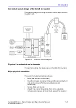
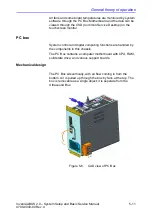
Interface ports and connectors on PC Box
USB ports
The PC sends its commands over USB to the motor control
board in the Scan Head and the motor control board in the
Weight Tower.
The PC motherboard USB ports used for this are connected by
cables to the Ultrasound Box MFEPS board USB ports
dedicated for this.
An additional normal USB 2.0 port connects the PC to the
Ultrasound Box's MFEPS power supply to allow the PC to
monitor MFEPS status.
Ethernet network port
The Ethernet port on the PC I/O panel is cabled to the NET and
USB relay board. That board line-isolates the Ethernet port.
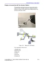
Touchscreen monitor cabling
The monitor has three cables:
1) Power cable (female plug end) to the PC Box ACDC board,
2) Display graphics cable (DVI-D) to the PC Box GPU,
3) Touchscreen signals cable to the PC Box (USB).
PCIe connector for cable to U/S Box cMST board
The PC Box has an external-mounted PCIe connector, that
provides signals to the PCIe cable between it and the U/S Box
cMST board.
Summary of Contents for H5018SC
Page 5: ...Invenia ABUS 2 0 System Setup and Basic Service Manual i 3 4700 0043 00 Rev 4 ...
Page 6: ...i 4 Invenia ABUS 2 0 System Setup and Basic Service Manual 4700 0043 00 Rev 4 ...
Page 7: ...Invenia ABUS 2 0 System Setup and Basic Service Manual i 5 4700 0043 00 Rev 4 ...
Page 8: ...i 6 Invenia ABUS 2 0 System Setup and Basic Service Manual 4700 0043 00 Rev 4 ...
Page 9: ...Invenia ABUS 2 0 System Setup and Basic Service Manual i 7 4700 0043 00 Rev 4 ...
Page 10: ...i 8 Invenia ABUS 2 0 System Setup and Basic Service Manual 4700 0043 00 Rev 4 ...
Page 11: ...Invenia ABUS 2 0 System Setup and Basic Service Manual i 9 4700 0043 00 Rev 4 ...
Page 12: ...i 10 Invenia ABUS 2 0 System Setup and Basic Service Manual 4700 0043 00 Rev 4 ...
Page 13: ...Invenia ABUS 2 0 System Setup and Basic Service Manual i 11 4700 0043 00 Rev 4 ...
Page 14: ...i 12 Invenia ABUS 2 0 System Setup and Basic Service Manual 4700 0043 00 Rev 4 ...
Page 15: ...Invenia ABUS 2 0 System Setup and Basic Service Manual i 13 4700 0043 00 Rev 4 ...
Page 16: ...i 14 Invenia ABUS 2 0 System Setup and Basic Service Manual 4700 0043 00 Rev 4 ...
Page 26: ...i 24 Invenia ABUS 2 0 System Setup and Basic Service Manual 4700 0043 00 Rev 4 ...
Page 277: ......
Page 278: ...1 2 Invenia ABUS 2 0 System Setup and Basic Service Manual 4700 0043 00 Rev 4 ...


