


GE M
EDICAL
S
YSTEMS
D
IRECTION
2392751-100, R
EVISION
3
V
IVID
™ 4 S
ERVICE
M
ANUAL
8-102
Section 8-6 - Lower Section Components Replacement
8-6-7-4
Up/Down/Swivel Handle Installation Procedure
NOTE:
This describes the procedure for installing the Up/Down/Swivel Handle (Part No. 237002).
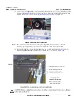
1) Place the new Up/Down/Swivel handle into the correct position on the handle mounting brackets
(fastened to the machine chassis) - refer to
2) Return the M6 Axis screw (previously removed) passing the end through the screw hole in the first
handle mounting bracket, through the two holes in the handle, then through the screw hole in the
second bracket - refer to
3.) Return the M6 nut (previously removed) to the handle assembly axis screw. Tighten the nut fully to
secure the handle assembly to the handle mounting brackets - refer to
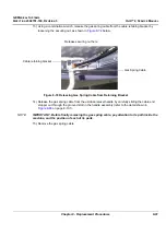
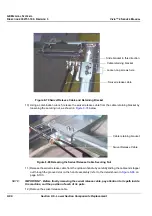
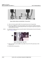
4.) Insert the gas spring cable end stopper through the grooved slot on the handle assembly carefully
aligning the groove on the cable with that of the groove in the slot (refer to the detail shown in
5.) Feed the gas spring cable down into the slot in the cable retaining bracket (refer to
below) and tighten the securing nut against the bracket to hold the cable firmly in position - refer
also to
6.) Repeat
to insert the swivel release cable end stopper into the grooved slot on the handle
assembly.
7.) Repeat
to secure the swivel release cable to the cable retaining bracket (
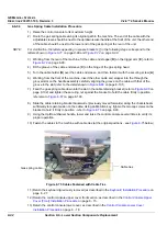
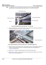
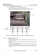
8.) Slide the cable retaining bracket
backwards
(previously moved forwards) along the chassis beam
sufficiently to regain tension on the cables. Using an M4 Allen key, tighten the two cap screws on
the bracket to hold it firmly in position - refer to
9) Test the Up/Down/Swivel handle to make sure the mechanism is operating properly and that the
handle is fastened securely on the chassis.
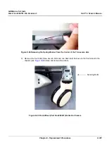
10.)Return the keyboard (previously removed) as described in the
Keyboard Installation Procedure
11.)Reconnect the four
keyboard matrix cables - refer to
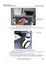
12.)Return the control console upper cover front section, as described in the
Cover (Front) Installation Procedure
13.)Return the control console lower cover, as described in the
14.)Return the control console lower cover rear, as described in the
Control Console Lower Rear Cover
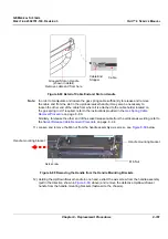
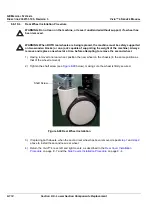
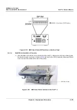
Figure 8-90 Swivel Release Cable Secured in Retaining Bracket
Cable securing nut
Cable retaining bracket