GE M
EDICAL
S
YSTEMS
D
IRECTION
2392751-100, R
EVISION
3
V
IVID
™ 4 S
ERVICE
M
ANUAL
Chapter 8 - Replacement Procedures
8-71
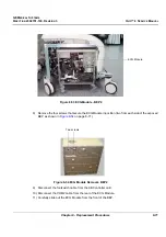
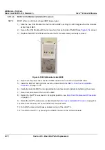
8) Remove the four screws that secure the ECG Module in position (two from each side of the exposed
BEP as shown in
9) Disconnect the footswitch cable from the KB Controller card.
10.)Disconnect the COM2 cable from the rear of the ECG Module.
11) Carefully slide out the ECG Module from the front of the BEP.
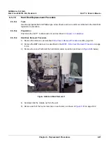
Figure 8-53 ECG Module - BEP2
Figure 8-54 ECG Module Removal- BEP2
ECG Module
Two screws


