GE M
EDICAL
S
YSTEMS
D
IRECTION
2317229, R
EVISION
3
LOGIQ™ 180 B
ASIC
S
ERVICE
M
ANUAL
5 - 12
Section 5-4 - Functional Subsystems
Section 5-4
Functional Subsystems
5-4-1
Front End Board
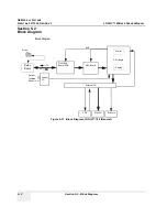
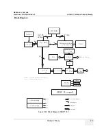
The Front End generates the strong transmit bursts, transmitted by the probes as ultrasound into the
body. It also receives weak ultrasound echoes from blood cells and body structure, amplifies the signals
and convert them to a 16 bit digital signal.
The digital representation of the signal is presented to DSC.
5-4-2
DSC Board
DSC (Digital Scan Converter) function is to convert analog data to digital data and stores in AFM
(Acoustic Frame Memory), then the Acoustic Frame Memory is transformed to X-Y plane memory
(XYM). While doing transformation from Acoustic Frame Memory to X-Y plane memory, it does Quad
point interpolation.
This also houses the electronics to display the plane memory data on NTSC or PAL TV monitor.
5-4-3
CPU Board
CPU Board Controls the overall system function including man-machine interface. It also has an
Overlay graphics controller which generates Overlay Graphics/Text for the screen. The Overlay data
output goes to the DSC Block.
The CPU performs the following functions:
1.) RTC for time and date
2.) DRAM for intermediate data storage
3.) EPROM for program memory
4.) Address Decoder for control signals
5.) Gain Encoder
6.) Overlay Graphics Controller and memory for overlay text data storage and manipulation
7.) TV Sync Generator for generating Sync and blank signal for composite video.
8.) It interfaces with Digital Scan Converter
9.) NV RAM for System Preset Parameters Storage
10.)Flash memory for storing upto 16 images. The CPU also interfaces with the Flash board (Optional
Module) which can increase the storage capacity to 112 images.The Back End Processor grabs the
data from the Image Port, stores it in a memory, performs scan.
.
5-4-4
Peripherals
VCR, Black & White Video Graphic Printer and Printer can be connected to the scanner. For more
details on recommended peripherals refer Chapter 3.


