


44
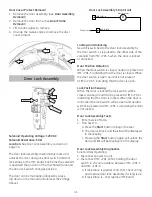
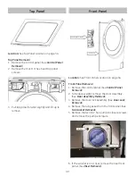
Control Panel Removal
1. Remove the cycle select knob by pulling it for-
ward.
2. Remove the knob retainer by pulling it forward.
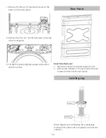
3. Remove the dispenser drawer by pulling drawer
outward while pressing down on the drawer
release.
Drawer Release
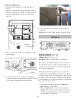
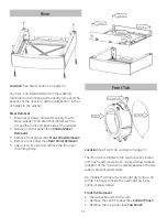
4. Remove the one T-20 and two #2 Phillips control
panel screws.
#2 Phillips
#2 Phillips
T-20
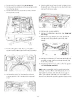
5. Pull the left side of the control panel slightly
forward (as shown below) and lift the left side up
fi
rst, then lift the right side up to remove.
6. Disconnect the UI wire harness and cut the UI
wire tie.
Note:
Install a new UI wire tie when reassembling.
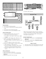
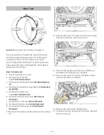
UI Board
Operating Voltage 1:
+12 VDC
Operating Voltage 2:
+7.5 VDC
COMM Voltage:
Pulsating DC
Location:
See UI Board Location on page 34.
The UI (User Interface) board provides a means of
communication between the washer and the con-
sumer. The UI board contains software algorithms
that control the washer.
When the UI board is replaced, a new model ID
number has to be programmed. Once the UI board
has been replaced, it may sometimes power up with
all of the UI LED’s blinking. If this is the case, follow
the steps below. If this is not the case, set the model
ID in service mode Test 02.
1. Simultaneously press and hold the
Temp
and
Spin
buttons for 3 seconds.
2. Press the
Soil
button to increase or press the
Temp
button to decrease the model ID selection
until the correct model ID number is displayed
per the table on next page.