


HARDWARE
24
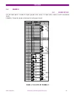
CIO Remote CAN Digital I/O Module
GEK-106465A
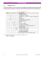
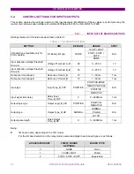
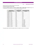
INTERNAL STATE
V 52/a
SUPERVISION
52 open
ON
Ok
52 closed
ON
Ok
TRIP
OFF
Ok if t < 0.5 s
TRIP with 52 open
OFF
Ok if t < 0.5 s
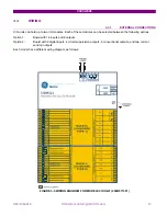
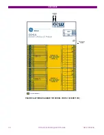
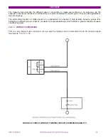
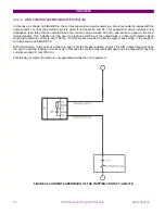
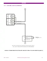
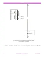
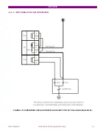
There is a possibility to monitor the trip circuit and trip coil continuity. This can be done by monitoring Vdc through the
output contact when this is open.
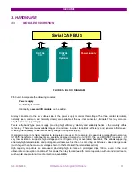
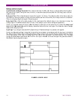
As shown on FIGURE 3-10, when the relay is not tripped, trip contact 35-36 remains open. If the breaker is closed, its
auxiliary contact 52a is closed. Therefore, a little current is flowing, about 2 mA, through terminals 15 and 16 through
the voltage detector circuit, which flows through 52/a and the tripping coil 52TC (TC = tripping coil). Current will only
circulate when there is continuity in the whole circuit, so the complete circuit is monitored, and not only the trip coil.
This circuit includes auxiliary 52/a as well as the whole wiring between the battery and the relay tripping terminals,
and between these and the breaker tripping circuit.
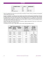
This is the first case shown on the table. With closed breaker, voltage is detected by V 52/a sensor, and this means
that there is continuity in the supervised circuit.
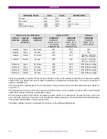
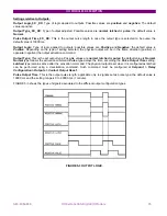
In this table, ON means that the voltage detector V52/a is active, detecting voltage presence.
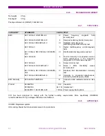
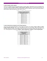
Status of Involved Elements
Input to F650
Decision
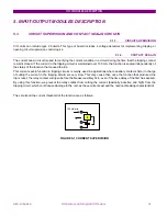
CIRCUIT
STATUS
OUTPUT
STATUS
(F35-F36)
BREAKER
STATUS
OPERAND
CONTACT
INPUT_00_10
(Va_COIL2)
V 52/a (F15-F16)
OPERAND
CONTACT
INPUT_00_15
(SUP_COIL2)
Healthy Open
52
closed
ON
ON
Healthy Open
52
open
ON
ON
Healthy Closed
52
closed
OFF
ON (if t < 500 ms)
OFF (if t > 500 ms)
Healthy Closed
52
open
OFF
ON (if t < 500 ms)
OFF (if t > 500 ms)
Faulty
Open
52 closed
OFF
OFF (500 ms delay)
Faulty
Open
52 open
OFF
OFF (500 ms delay)
Faulty
Closed
52 closed
OFF
OFF (500 ms delay)
Faulty
Closed
52 open
OFF
OFF (500 ms delay)