GE GEC-4VDPBC Installation Sheet Download Page 3

P/N 1069686 • REV 1.0 • ISS 10MAR10 

3 of 11 


Wiring Technical Notes 

These technical notes should all be considered prior to installing these devices. 

•  Use point to point unshielded twisted pair wire 24-16 AWG (0, 5-1, 3 mm) 

stranded or solid, Category 2 or better. 

•  The video signal may coexist in the same wire bundle as other video, 

telephone, data, control signals, or low-voltage power. You can run GE video 
signals in or near electromagnetic fields (in accordance with National 
Electrical Code, local or other local safety requirements). 

•  DO NOT USE SHIELDED TWISTED PAIR WIRE. Multi-pair (8 pair or more) wires 

with an overall shield are fine. 

•  DO NOT USE UN-TWISTED WIRE. 

•  DO NOT place a transmit and a receive signal in the same wire bundle. It 

may cause interference. 

•  DO NOT send 

Up-the-Coax

 Pan/Tilt/Zoom signals through active (amplified) 

GE transmitters or receivers. Passive GE transceivers can transmit video and 

Up-the-Coax

 P/T/Z control signals up to 750 ft. (228 m). 

•  We recommend using short 18 AWG solid wires for ground connections. 

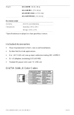
•  GE VPD products follow the EIA/TIA 568 standard. There are two wire color-

code standards: EIA/TIA 568A and EIA/TIA 568B. Either standard can be used 
for making connections as long as the RJ-45 jacks at both ends of each 
cable follow the same standard. 

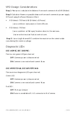
•  Measure wire distance by: 

1.  Shorting the two conductors together at the far end, and measuring 

the loop-resistance by an Ohmmeter.  

2. Use 

the 

Loop Resistance

 table to calculate the distance. 

•  DO NOT connect coax cables longer than 100 ft. (30 M) to the BNC 

connectors of any GE UTP equipment. 

•  All measured distances should include any coax cables in the path. 

•  Verify camera current requirements and wire resistance limits for the 

maximum distance that power can travel. Use the 

Power Distance Chart

 to 

verify the wire distance. 

•  GE VPD products require Unshielded Twisted-Pair (UTP) wires Category 2 or 

better, 24 AWG (0,5 mm) or thicker. 

Summary of Contents for GEC-4VDPBC

Page 1: ...8PVPDTCHUB and GEC 16PVPDTCHUB come with built in 8 and 16 channel fully isolated class II 24 28 VAC power supplies Each camera power output in addition to an auto reset fuse is equipped with a 2 A g...

Page 2: ...s been damaged in any way such as a power supply cord or plug is damaged liquid has been spilled or objects have fallen into the apparatus the apparatus has been exposed to rain or moisture does not o...

Page 3: ...vers Passive GE transceivers can transmit video and Up the Coax P T Z control signals up to 750 ft 228 m We recommend using short 18 AWG solid wires for ground connections GE VPD products follow the E...

Page 4: ...ation should be made by a qualified service person and should conform to all local codes DO NOT bundle UTP signals in the same conduit as high voltage wiring To reduce the risk of fire or electrical s...

Page 5: ...onnect the Data UTP pigtail Black White of the GE single combiner receiver to the data connector of the camera There is no data connection on GEC VCR Power Connect the power UTP pigtail Black Red of t...

Page 6: ...eiver unit Video Use provided 2 ft 60 cm coax patch cords to connect the BNC video inputs of video receiving devices such as DVRs or matrix switches Data Connect each RJ 45 data connector to a Cat 5 c...

Page 7: ...id span location closer to the cameras Use an active receiver hub at control room Step 3 Use a single channel GE combiner transceiver on the camera side considering the camera voltage Diagnostic LEDs...

Page 8: ...lt Protection 2 A 5x20 mm type T fuse front access plus a 2 5 A self resetting fuse at per channel Main fuse 4 A at 115 VAC 3 A at 220 VAC 5x20 mm GEC 8PVPDTCHUB 7 A at 115 VAC 5 A at 220 VAC 5x20 mm...

Page 9: ...oncondensing Temperature Operating 10 to 50 C Storage 30 to 70 C Specifications are subject to change without notice Included Accessories Mounting brackets for front rear or wall installations Rubber...

Page 10: ...1069686 REV 1 0 ISS 10MAR10 Camera side RJ 45 Connections Control Room Data Connections Figure 2 GEC 4VDPBC Cameras 1 4 only 16VDPBC 8PVPDTCHUB 16PVPDTCHUB Cameras 1 8 Figure 3 GEC 16VDPBC 16PVPDTCHUB...

Page 11: ...owever there is no guarantee that interference will not occur in a particular installation If this equipment does cause harmful interference to radio or television reception which can be determined by...

Reviews: