background image

g


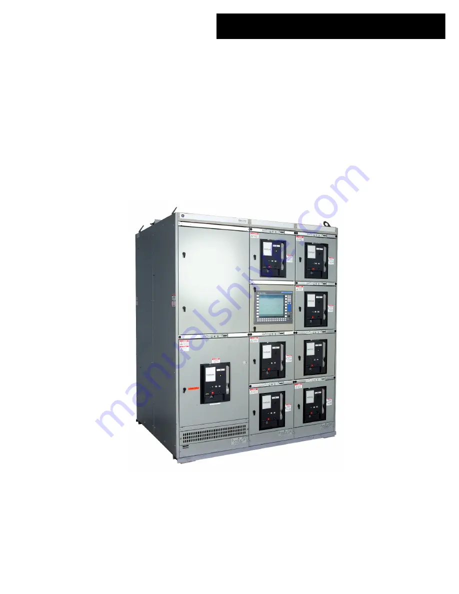
GE Entellisys™ Low Voltage


Switchgear


________________________________________________ 


Installation and Maintenance Instructions


 DEH-237                                                          R01 

BCS Switchgear Inc.

Switchgear | Circuit Breakers | Parts | Tech Support

bcsswitchgear.com | 888.599.0486

Need Help? 888.599.0486

Summary of Contents for Entellisys

Page 1: ...itchgear ________________________________________________ Installation and Maintenance Instructions DEH 237 R01 BCS Switchgear Inc Switchgear Circuit Breakers Parts Tech Support bcsswitchgear com 888 599 0486 Need Help 888 599 0486 ...

Page 2: ...BCS Switchgear Inc Switchgear Circuit Breakers Parts Tech Support bcsswitchgear com 888 599 0486 Need Help 888 599 0486 ...

Page 3: ...uracy the information contained herein does not cover all details or variations in hardware and software nor does it provide for every possible contingency in connection with installation operation and maintenance Features may be described herein that are not present in all hardware and software systems GE Consumer Industrial assumes no obligation of notice to holders of this document with respect...

Page 4: ...quipment Installation 4 1 General 24 Site Location 24 Foundation Requirements 24 Foundation Preparation 24 4 2 Assembly and Installation of Switchgear Equipment 27 General Requirements 27 Detailed Assembly and Installation Instructions 27 Anchoring Switchgear Equipment 33 Busway Connections 35 Control Wire Connections 35 Power Cable Connections 36 Breaker Hoist 37 Final Inspection 38 4 3 Installat...

Page 5: ...6 20 Shutter Unit 59 Installing a EG 32 40 50 Fuse Rollout Shutter Unit 59 Chapter 8 Energizing the Switchgear 8 1 Before Energizing 60 8 2 Energizing Procedures 60 Chapter 9 Maintaining the Switchgear 9 1 Maintenance Requirements 61 General 61 9 2 Breaker and Instrument Compartments 61 Breakers 61 Test for Proper Operation 61 Checks after Breaker is De energized 61 Lubrication 62 Entellisys Instr...

Page 6: ......

Page 7: ...t and its components Chapter 2 Receiving Handling and Storage describes procedures required for receiving and handling the equipment and how to prepare it for short or long term storage Chapter 3 Description describes the Entellisys Low Voltage Switchgear and its various components Included are the section enclosure breaker compartment circuit breakers instrument panels and instrument compartments...

Page 8: ...gement drawings including front view and floor plan 2 Elementary and connection drawings or wiring routing tables which identify test and connection points including terminal blocks device studs switch contact developments and remote connections 3 Summary of all the components furnished with the switchgear including the breakers identified by catalog number These are all documents necessary to ins...

Page 9: ... list will indicate the appropriate section number in which they are stored Large items such as hoist dollies and hoist carriages used with indoor equipment will always be shipped in separate crates or cartons See Fig 2 2 Inspecting for Damage All equipment leaving the factory is carefully inspected and packed by personnel experienced in the proper handling and packing of electrical equipment Upon...

Page 10: ...The crane and the four lift cables must have a minimum load lifting capacity of 10 000 pounds NOTE The angle between the cables and the top of the equipment must be at least 45 degrees If this is not possible because of lack of headspace spreader bars must be used Also lift cables with greater load capability may be necessary depending upon the angle between the cables and the crane hook NOTE Il f...

Page 11: ...e feet long Use one roller for each 18 inches of equipment length Forklifts When using a forklift to raise the line up to position rollers underneath proceed as follows 1 Expand forklift tines to their maximum widest extension 2 Carefully insert tines of forklift below one side of the switchgear line up at the approximate center of the panel as shown in Fig 2 4 NOTE Do not attempt to lift or move ...

Page 12: ...so may result in serious damage to the switchgear equipment ATTENTION Il ne faut pas placer de vérins en aucun endroit autre que les coins avants et arrières du dispositif de commutation L équipement peut être sérieusement endommagé si l on ne respecte pas cette directive 2 Raise the switchgear evenly and just enough to position a roller beneath the equipment Gently lower the switchgear onto the r...

Page 13: ...watts of heat in each section is required Incandescent lamps may be used for this purpose These lamps should be located in the bottom breaker compartment of each section and supported so the bulbs will not touch adjacent materials CAUTION If the space heaters are to be temporarily energized from an external source it is important to remove the fuses on the secondary side of the control power trans...

Page 14: ...a side view of a typical section showing compartmentalization 3 2 Summary Description General Electric Entellisys Low Voltage Switchgear is a freestanding assembly of metal enclosed sections containing low voltage power circuit breakers bus bars cable termination provisions and Entellisys instrumentation It may also be an integral part of a load center unit substation either single ended or double...

Page 15: ...ary breaker contacts interlocks and EntelliGuard Messengers The breakers are provided with self aligning primary and secondary disconnect contacts and a breaker mechanism locking unit The individual sections compartments and devices are described in the following paragraphs Fig 3 2 is an outline of a typical single ended load center unit substation illustrating the nomenclature used for all equipm...

Page 16: ...EH 231 Entellisys Low Voltage Switchgear System User s Manual for further instructions Each Entellisys low voltage switchgear lineup contains standard devices housed within the instrument compartments Two CPUs Central Processing Units provide the processing capability to support all switchgear functions At least one HMI Human Machine Interface provides user access to the Entellisys system Network ...

Page 17: ...ave any ventilation slots thus protecting operators from hot ionized gases that may be vented by the breaker during circuit interruption Additionally the breaker compartment Fig 3 5 is enclosed by grounded steel barriers on the top sides bottom and front In the back a flame retardant track resistant glass filled polyester base minimizes the possibility of fault communication between compartments o...

Page 18: ...ion 1 Side barrier 6 Primary disconnects load 2 Bottom barrier 7 Drawout rails 3 Rear base barrier 8 Racking anchor pins 4 Primary disconnects line 9 Secondary Disconnect 5 Current Transformers Fig 3 5 Circuit breaker compartment 22 inch 1 3 6 4 8 5 7 7 2 9 ...

Page 19: ...ments of multi source lineups The shutters are constructed from glass reinforced polyester insulating material NOTE If a fuse rollout FRE carriage is used with an EGF 32 40 50 circuit breaker whose compartment is equipped with shutters the FRE compartment will also be equipped with shutters NOTE Si on utilise un chariot porte fusibles à roulettes avec un disjoncteur EGS 32 40 50 dont les compartim...

Page 20: ...ows the shutter assembly with the shutters manually retracted to show the location of the primary disconnect stabs 5 behind the shutter assembly Circuit breakers mounted in 22 inch wide compartments EG 08 EG 16 EG 20 are supported on drawout rails 7 Fig 3 5 Larger EG 32 and EG 40 circuit breakers and fuse rollout carriages are installed in 30 inch wide compartments and are supported on drawout rai...

Page 21: ...ntinuous or interrupting current ratings may be substituted for those having lesser ratings The compartment however retains the factory configured ratings and protection settings Substitution of manual for electric or electric for manual EntelliGuard breakers is not recommended 1 Racking arm 2 Secondary disconnects 3 Racking screw Fig 3 9 EGS 40 circuit breaker Each breaker compartment has four po...

Page 22: ...s for either manual or electrical operation Six General Electric EntelliGuard Circuit Breakers form the complete family of breakers used in the Entellisys switchgear These circuit breakers range from 800 to 5000 ampere frame sizes and are built with the following ratings and characteristics EGS EGH EGX 08 Circuit Breaker 800 ampere frame size Standard 30 000 ampere interrupting and short time capa...

Page 23: ...ed IC and short time rating 100 000 amperes EGX 50 at 480 volts 3 7 Fuse Rollout Elements When the system available short circuit current exceeds the unfused breaker ratings current limiting fuses can be used in series with EGF 20 EGF 32 EGF 40 and EGF 50 breakers to increase the short circuit rating of the combination to 200 000 amps When used such fuses are housed in a separate drawout compartme...

Page 24: ...rimary disconnect stabs 3 9 Auxiliary Transition Sections Sections may be provided for any one or more of several reasons including Transition to a close coupled transformer Incoming cable or busway when a main breaker section is not provided Auxiliary sections may be 22 inch 30 inch or 38 inch wide as required to accommodate the space requirements The compartment doors on the front of the section...

Page 25: ...arrangement is shown in Fig 3 15 The standard bracing is 65 000 amperes RMS symmetrical Bracing for 100 000 150 000 and 200 000 amperes RMS symmetrical is available as an option In general when the switchgear equipment has no more than four sections or does not exceed 10 feet in length it will be shipped as one complete lineup In such cases the only field assembly would be to a close coupled trans...

Page 26: ...us System A bus insulation system Fig 3 16 that fully insulates each phase of the horizontal main bus and isolates each phase of the vertical bus is optionally available for Entellisys switchgear when specified With the INSULATED ISOLATED BUS system there are no live connections accessible in the rear of each section except the cable lugs 1 Vertical riser bus covers 2 Run backs to feeder cables 3 ...

Page 27: ... and isolation of the vertical riser bus bars 2 Fig 3 18 is provided by installing phase isolation barriers 3 between the bus bars and by mounting covers 4 over the bus bars The top portion of the vertical bus is shown with the cover removed The phase isolation barriers and riser bus covers are constructed from insulating material Insulation of the horizontal main bus bars 5 is achieved by an oven...

Page 28: ...terminations The cable bending space meets the requirements of the 2005 National Electric Code Various arrangements of single or double cable terminals are provided depending upon the purchaser s requirements 1 Support rack for customer s feeder cables 2 Cable lugs mechanical type 3 Cable lugs compression type Fig 3 20 Cable termination provisions When specified racks 1 Fig 3 20 for the support of...

Page 29: ...eneral Electric Entellisys switchgear sections are grounded to the internal equipment ground bus 4 Fig 3 21 located at the bottom of the cable compartment 1 Feeder runbacks 2 Vertical riser bus covers 3 Horizontal main bus 4 Ground bus Fig 3 21 Cable termination compartment 1 3 4 2 ...

Page 30: ... and or procurement of equipment phases Indoor locations within buildings impose certain requirements that must be met so that the switchgear may operate efficiently with a minimum of maintenance In locating the Entellisys Switchgear adequate aisle space must be provided at the front and rear of the equipment to ensure proper ventilation of the equipment and to allow service and maintenance of the...

Page 31: ...or channels under the front and rear switchgear anchor points see Fig 4 2 should be embedded in a level concrete slab with their top surfaces flush with the finished floor It is essential that these steel channels be level and aligned with each other prior to final anchoring to prevent distortion of the switchgear structure to assure proper mechanical and electrical connections between shipping sp...

Page 32: ... of the standard enclosures available for Entellisys Switchgear Fig 4 3 illustrates the space available for conduit and or cable entrance through the bottom or top of each equipment section The space required for control wiring entry to the optional wiring trough is also shown NOTE BUS COMPARTMENT BARRIER LOCATION WHEN THIS OPTION IS PROVIDED IT REDUCES AVAILABLE SPACE FOR CABLES ABOVE BY 5 INCHES...

Page 33: ...ue la fondation soit absolument au niveau et exempte de débris afin de prévenir des dommages à l équipement du dispositif de commutation Detailed Assembly and Installation Instructions The recommended procedure for installation of a switchgear or Load Center Unit Substation is as follows 1 POSITION THE EQUIPMENT Position the equipment or sections of the complete equipment in their final location F...

Page 34: ...E THE SHIPPING SKIDS The equipment is fastened to the shipping skids with 3 8 3 lag screws through the equipment anchoring holes See Fig 4 5 Equipment shipping sections up to 10 feet long will be fastened to the skids with four lag screws one in each corner Longer sections will have two additional lag screws which are located near the middle of the equipment The shipping skid and lag screws are ex...

Page 35: ...d with a torque of 25 30 ft lbs 4 COMPLETE THE ELECTRICAL INTERCONNECTIONS After completing the mechanical connections between the several sections of equipment the electrical interconnections should be completed This includes the installation of splice plates for the main bus bars the neutral bus and the ground bus in addition to the Entellisys control and communication circuitry WARNING All swit...

Page 36: ...e installation Fig 4 9 illustrates the installation of the ground bus splice plate across a shipping split In addition to the bolted fastening of the splice plate to the two ends of the ground bus self tapping 1 4 20 bolts pass through the splice plate and ground bus stubs and thread into the equipment frame These bolts should be fastened with a torque of 7 9 ft lbs If a GE transformer rated above...

Page 37: ...l splice plate Fig 4 11 Plan view of neutral bus splice installation The installation of the horizontal bus splice bars is with bolted joints Figs 4 12 and 4 13 illustrate the assembly of the main bus splice plates on the bolted bus system Copper bus systems are normally supplied with flat washers and lock washers Fig 4 12 shows the rear view of the main bus area with the installed splice bus indi...

Page 38: ...ening the 13 bolts fastening the transformer connection straps to the incoming bus bars is 35 40 ft lbs 6 INTERCONNECT ENTELLISYS CONTROL AND COMMUNICATION WIRING Interconnection of control wiring across shipping splits is accomplished by connecting to terminal blocks located in the cross section wiring trough on top of the equipment shown in Fig 4 14 Ethernet cables are connected by similarly rou...

Page 39: ... 2 It is recommended that two welds each 2 1 2 inches long min be used for each section to firmly tie the bottom width post 3 to the channel sill b The rear of the equipment may be anchored by one of three procedures The first method is by plug welds 4 Fig 4 15 using the anchor bolt holes in the rear sill angle 5 The plug weld should receive a minimum 1 2 inch bead around the entire circumference ...

Page 40: ...Low Voltage Switchgear Chapter 4 Equipment Installation 1 Channel sill 2 3 16 inch fillet weld 3 Front width post 4 Plug weld in anchor bolt hole 5 Rear sill angle 6 Rear width post Fig 4 15 Equipment weld anchoring ...

Page 41: ... contact soient unduites d une pellicule de graisse lubrifiante GE D6A15A2 L équipement est fourni avec une boîte de cette graisse Il ne faut pas graisser les fils des boulons car la force de serrage exercée par le boulon en sera affectée The recommended torque for tightening the 1 2 13 NC bolts connecting the busway stub conductions to the riser bus power connectors is 35 40 ft lbs Control Wire C...

Page 42: ... See Appendix A Table A 2 For aluminum cables wire brush the wire strands thoroughly Immediately after wire brushing coat the cable strands with a quality oxide inhibiting compound such as Penetrox A Insert exposed wires into the terminals and tighten the set screws in accordance with values shown in the torque Table A 2 in Appendix A of this Instruction Book CAUTION The torque values shown in the...

Page 43: ...embly on the switchgear equipment it is necessary to remove the runner guide from the hoist carriage as shown in Fig 4 20 Do not dispose of this guide since it must be reinstalled after mounting the hoist on the equipment NOTE Maximum recommended lifting capacity is 700 lbs NOTE La capacité maximale recommandée de soulèvement est de 700 livres Fig 4 18 Breaker hoist assembly Fig 4 19 Carton contai...

Page 44: ...ers positioned on front track Fig 4 23 Replacing the runner guide after completion of hoist installation Fig 4 24 Removing the bracket locking the hoist dolly If the equipment has been shipped in sections run the hoist carriage over the assembled shipping split to check the alignment of the hoist rail and runner If necessary adjust the rail and or runner for smooth operation of the rollers on the ...

Page 45: ...ure using 3 8 inch bolts flat washers and if the bolts are not self threading lock washers and nuts To ensure proper sealing and enclosure protection rating use the provided sealing washers Install the sealing washers inside the enclosure with the tapered cone against the enclosure and then add the flat washers as shown in Figs 4 26 and 4 27 4 Attach a suitable conduit fitting to the hole from Ste...

Page 46: ...40 Entellisys Low Voltage Switchgear Chapter 4 Equipment Installation Fig 4 28 HMI enclosure and devices RS232 RS485 Converter Terminal Block Power Supply Ethernet port Areas suitable for conduit hole ...

Page 47: ...he proper compartment refer to the breaker location list on the front view drawing Find the proper breaker by the identification card on the breaker carton or the mark number on the breaker nameplate All identical breakers will have the same mark and catalog number EGX 08 SETTING Fig 5 1 Rejection pin mounting used in EG 08 16 20 compartments Rejection Feature Drawout breakers of the same type and...

Page 48: ...ockwise Précautions Vérifier le compartiment afin de s assurer qui il est libre d objets étrangers Vérifier que le disjoncteur est du genre correct pour ce compartiment Assurez vous que le disjoncteur est en position OPEN Appliquer une mince couche fraîche de graisse lubrifiante GE D6A15A2 aux débranchements primaires du disjoncteur Assurez vous que les cames de montage du disjoncteur soient posit...

Page 49: ...t Breakers Fig 5 4 Reel out hoist cable Attach spreader bar assembly to circuit breaker Fig 5 6 Pull rails out completely from the circuit breaker compartment Fig 5 5 Hoist breaker above rails Fig 5 7 Lower the breaker onto the rails of the cell Remove the spreader bar assembly ...

Page 50: ...mpartment until the racking forks meet the racking pin this is the DISCONNECT position If an incorrect breaker has been installed the interference pins on the breaker will interfere with the rejection pins in the compartment prior to reaching the DISCONNECT position See Fig 5 8 At this point the racking forks are contacting the fixed racking pins in the compartment 7 Slide rails back into compartm...

Page 51: ...evation of the rails See Fig 5 5 4 Pull the drawout rails all the way out to its WITH DRAWN limit The rail pin will be positioned at the back of the rail slot 5 Slowly lower and guide the breaker to allow the 4 breaker wheels to align with the rails See Fig 5 7 Remove the lifting device The breaker is now positioned on the drawout rails 6 Roll the breaker into the compartment until the racking cam...

Page 52: ...ent 8 Lower the breaker onto a flat surface free of protrusions that could damage the breaker s internal parts The back of breaker will be resting on the interference pins and guide 5 5 Removing the EGS 32 40 50 Circuit Breakers WARNING Do not stand under the circuit breaker during the lowering operation ADVERTISSEMENT Il est interdit de se tenir sous le disjoncteur durant l opération de levage CA...

Page 53: ...e range of fuse sizes available for these breakers including catalog numbers of Ferraz Shawmut Fuses Class J fuses rated 300 through 600A have one mounting hole per tang The 300 350 and 400A sizes require copper adapter bars as shown in Fig 5 13 Fig 5 12 Typical mounting for Class L fuse on EGF 08 16 breakers Fig 5 13 Mounting for 300 350 and 400 ampere Class J fuses on EGF 08 breakers A special f...

Page 54: ...cing the fuse in the right pole plan view of the breaker note particularly that this fuse is mounted differently from the other two fuses As shown in Fig 5 15 for this phase the fuse is rotated 180 degrees about its axis so that its inboard tang is positioned beneath the breaker stud This tang is offset with respect to the opposite end Fig 5 16 so that rotating the fuse does not alter the position...

Page 55: ...his panel can be opened to allow access to the fuses Fig 5 18 only when the FRE is in the WITHDRAWN position In all other positions an interference plate attached to the right side of the panel prevents it from being opened Operation of the breaker compartment keylock is the same for all models With the breaker open the key can be removed this extends the lock bolt thereby maintaining the breaker ...

Page 56: ...rtment key interlock mechanism Secondary disconnects on the FRE provide the voltage signals across each fuse to the OPEN FUSE LOCKOUT DEVICE on the associated circuit breaker Fig 5 21 Fig 5 19 View showing FRE key interlock locking FRE in connect position Fig 5 20 Key is captured in key interlock until breaker is opened Fig 5 21 View showing Open Fuse Lockout Device on the associated breaker ...

Page 57: ...it the IEEE factory test voltage is two times switchgear rating plus 1 000 volts See Table 6 1 Potential and control power transformers must be disconnected during high voltage testing Switchgear Voltage Rating ANSI Test Voltage AC RMS Field Test Voltage AC RMS 600V 480V 240V 2200V 1960V 1480V 1650V 1470V 1110V Table 6 1 6 2 Key Interlocks After initial installation of the switchgear equipment all...

Page 58: ...Disconnect all control circuits before checking resistance 3 Check for secure mounting and wiring connections at Entellisys instrumentation 4 Using the Entellisys HMI exercise all EntelliGuard breakers to determine all devices work correctly See DEH 231 for instructions on using the Entellisys HMI 5 Test all protection functions using the Entellisys System Test Kit See DEH 233 for instructions 6 M...

Page 59: ...ellisys HMI Electrically Operated Breakers The breakers may be closed by a mechanically operated double insulated push button switch on the breaker escutcheon or by the Entellisys HMI Fuses are located in the breaker compartment just behind the door Electrically Opening EntelliGuard Breakers Electrically operated EntelliGuard breakers are equipped with both a shunt trip and a flux shifter for open...

Page 60: ...the breaker escutcheon gives the position of the breaker as it moves through the door cutout 7 3 Front Doors Operation The front access doors on all standard Entellisys Switchgear are hinged and equipped with a turn latch Fig 7 3 To open the door rotate the knob clockwise turn Removal and Installation Refer to Fig 7 3 and remove install switchgear front doors Door Removal To remove the Entellisys ...

Page 61: ... Key Interlock Operation Check The operation of the key interlock should be checked as follows 1 With the breaker in the CONNECT position manually trip the breaker This then allows the interlock trip slide to be pushed in When the trip slide is in the lock bolt may be extended and the key removed The breaker will remain trip free in the CONNECT position until the key is returned and the lock bolt ...

Page 62: ...breaker from its locked position 3 Align the appropriate hasp front hasp for DISCON NECT position or rear hasp for the TEST position insert and lock the padlock Fig 7 8 Compartment padlock device EG 08 16 20 EG 32 40 50 EG 32 40 50 FRE compartments Padlocking the EG 08 16 20 EG 32 40 50 EG 32 40 50 FRE Compartments See Fig 7 8 1 The circuit breaker compartment door must be opened to put the padloc...

Page 63: ...roper precautions are taken the removal of a shutter unit presents the hazard of electrical shock and burn Do not remove the shutter unit unless the equipment has been de energized Failure to do this can result in serious injury ADVERTISSEMENT A moins que les précautions nécessaires ne soient prises l installation d une unité à volet présente des risques de choc électrique ou de brûlure Il ne faut...

Page 64: ... twelve wires from the two terminal blocks and then remove the inch hex head screws from the enclosure 3 Take out two 1 4 inch hex head screws on each side of the frame A socket wrench with a 3 8 inch driving head with 4 inch extension will be needed 4 Carefully remove the entire shutter frame 5 The frame is then maneuvered forward past the cam plates on each side then upward and forward over the ...

Page 65: ...of the shutter frame against the vertical stringers at the rear corners of the compartment 3 Align the holes in the flange and drive in four 1 4 inch hex head screws using a 3 8 inch driver and a socket wrench with a 4 inch extension 4 If it was present reinstall the Clamp Circuit Reconnect the 12 wires in the same positions as they were before Reattach the enclosure to the side sheet using inch h...

Page 66: ...s caused by damage or poor installation practices have not been detected in the checkout procedure described previously serious damage can result when power is turned on ATTENTION La mise sous tension pour la première fois d un dispositif de commutation est un acte potentiellement dangereux Il faut donc que du personnel qualifié en électricité soit présent lorsque l équipement est mis sous tension...

Page 67: ...ts as well as outside sources are disconnected ADVERTISSEMENT Il faut que l équipement primaire soit complètement désamorcé lorsque des tests sont effectués sur des circuits de contrôle etc Assurez vous que toutes les aires de rétroaction des circuits secondaires de même que les sources extérieures soient débranchées 2 Remove the breakers from their compartments to a clean maintenance area Close c...

Page 68: ...ubricant D6A15A1 5 Before replacing the breaker wipe off the primary disconnecting device contacts Apply a thin coat of GE lubricant D6A15A1 to the stationary studs and to the primary disconnects on the breaker 9 3 Bus Area WARNING De energize equipment completely before doing maintenance work on any devices connections bus work breaker or feeder cable compartments This includes de energizing any ...

Page 69: ...aced if any signs of deterioration are evident 9 6 Paint Refinishing Indoor switchgear is finished with ANSI 61 gray acrylic enamel paint To refinish damaged areas remove all loose paint rust scale oil or grease Sand any scratches smooth using 220 grit paper or finer Apply a coat of acrylic enamel primer with a viscosity of approximately 24 32 seconds using a 2 Zahn cup Reduce with thinner if need...

Page 70: ...que values are for non lubricated threads Caution should be exercised when installing parts or components to the compartment molded base Torque 1 4 inch screws slowly and do not exceed nine ft lbs Table A 2 Torque Values for Self threading Screws in Plastic Wire Size Torque in lbs 6 5 4 3 100 3 2 1 125 0 00 150 000 0000 200 000 200 250 000 300 000 350 000 400 000 250 500 000 600 000 700 000 750 00...

Page 71: ...r mounted rejection plate 22 inch Wide Compartment Figure B 1 EG 08 16 20 breaker family shows the breaker mounted rejection tabs located on the bottom left side of the backframe When a wrong type breaker is inserted into a compartment the breaker tabs and equipment pins interfere preventing the breaker from rolling into the DISCONNECT position Breakers may be interchanged in one direction only Sp...

Page 72: ... l l l l EGF 16 2500A l l l l l EGF 16 2500A l l l l EGS 20 l l l l l EGF 20 l l l l l l l Pin No Pin Fig B 2 Rejection pin pattern code for EG 08 16 20 breakers The rejection tabs logic shown above is for EntelliGuard breakers only Rejection pin patterns on the breakers prevent their installation into AKD 10 equipment compartments Likewise rejection pins in Entellisys equipment compartments preve...

Page 73: ... 32 or EGX 40 can be inserted into an EGH 32 compartment 3 An EGX 40 can be inserted into an EGX 32 compartment 4 An EGF 40 can be inserted into an EGF 32 compartment 5 An EGX 40 or EGF 40 may be inserted into an EGS 40 compartment 6 An EGX 50 or EGF 50 can be inserted into an EGS 50 compartment Figure B 3 shows the rejection pin combinations for 3200A 4000A and 5000A breakers and fuse rollout ele...

Page 74: ...g EG 32 40 50 rejection angles Fuse Rollout Elements Fuse rollout FRE elements used in conjunction with the EGF 32 3200 ampere EGF 40 4000 ampere or EGF 50 5000 ampere breakers employ the same type drawout mechanism as their companion breakers and utilize the same type of rejection system Only a 3200 ampere fuse rollout element may be installed in a 3200 ampere fuse rollout compartment only a 4000...

Page 75: ...GF 20 600 480 240 65 65 65 65 65 65 65 65 65 3200 EGS 32 EGF 32 600 480 240 65 65 65 65 65 85 65 65 65 3200 EGH 32 600 480 240 85 85 85 85 85 130 85 85 85 3200 EGX 32 600 480 240 85 100 100 85 100 130 85 100 100 4000 EGS 40 EGF 40 600 480 240 85 85 85 85 85 130 85 85 85 4000 EGX 40 600 480 240 85 100 100 85 100 130 85 100 100 5000 EGS 50 EGF 50 600 480 240 85 85 85 85 85 130 85 85 85 5000 EGX 50 6...

Page 76: ...osing springs have been charged It is always provided on electrically operated breakers The catalog number and operating voltage for the Remote Close accessory are listed in Table D 2 For installation instructions see DEH 172 or DEH 173 Breaker Rating Catalog Number Voltage Rating 800A 2 000A WPRCSF60120 120 Vac 60 Hz 3 200A 5 000A WPRCLF60120 120 Vac 60 Hz Table D 2 Catalog number and operating v...

Page 77: ...larm with Lockout status contact to its normal configuration and allow the breaker to be closed Figure D 4 Bell Alarm with Lockout connections to the Secondary Disconnect The contact is shown in the reset state Network Interlock The Network Interlock provides a means of locking out a breaker to coordinate its operation with other breakers in the distribution network When activated by the EntelliGu...

Page 78: ...ry standards have been established for the minimum performance that is indicated in Table F 1 With adequate maintenance GE breakers can be expected to exceed the standards Circuit Breaker Frame Size Amperes Number of Operations Between Servicing Number of Operations Rated Continuous Current Switching 1 2 3 4 5 6 7 8 and 10 Number of Operations No Load Closing and Opening 1 2 3 4 5 6 and 7 Number o...

Page 79: ...g of the circuit breaker at voltages up to the rated maximum voltage and at 85 power factor or higher 9 When closing currents up to 600 and opening currents up to 100 80 power factor or higher of the continuous current rating of the circuit breaker at voltages up to the rated maximum voltage When closing currents up to 600 and opening currents up to 600 50 power factor or less of the continuous cu...

Page 80: ...g GE Consumer Industrial General Electric Company 510 Agency Road West Burlington IA 52655 DEH237 R01 1205 2005 General Electric Company ...

Reviews: