background image


Page 

20

 of 

79


[EN] English – K0571 Issue 1 

User Manual 

Druck DPI611 

1.12


DRUCK DPI611, MODES 

1.12.1


Power ON 

From 

OFF

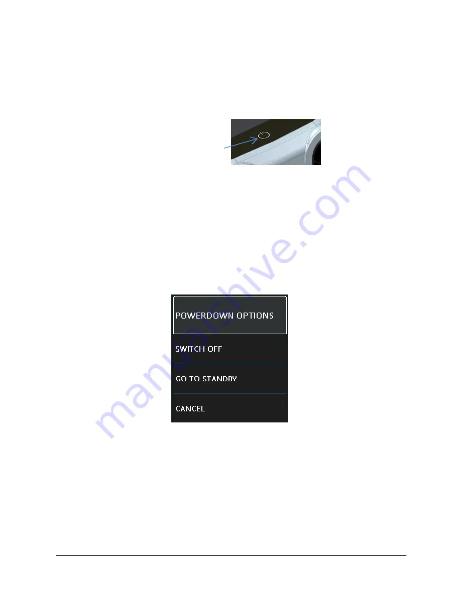
 – momentarily press the power button until the GE 

Logo appears.


Figure 1-8 Power Button 


1.12.2


Power OFF 


Press and Release the Power Button: 

Select SWITCH OFF from the POWERDOWN OPTIONS window 

displayed. 


Figure 1-9 Power Down Options 


SWITCH OFF

 – Full power down of DPI611 – Recommended if 

unit  is  not  going  to  be  used  for  several  hours  (Requires  full 

reboot on next power up). 

        Power ON/OFF 

Summary of Contents for Druck DPI611

Page 1: ...to change without notice GE is a registered trademark of General Electric Company Other company or product names mentioned in this document may be trademarks or registered trademarks of their respective companies which are not affiliated with GE Druck DPI611 Portable Pressure Calibrator User Manual K0571 ...

Page 2: ...or revised information The most recent publication can be determined by comparing the last three characters at the end of the part number and the date issued DPI 611 Portable Pressure Calibrator User Manual Part Number K0571 Revision Level Date Issued General Description of Changes Issue 1 13 08 14 Initial release ...

Page 3: ...TAGE CATEGORY 11 1 8 PREPARING THE INSTRUMENT 11 1 8 1 Initial Checks 11 1 8 2 Install the Battery 12 1 9 PARTS 13 1 9 1 Test Port 14 1 9 2 Pneumatic Pressure Release Valve 15 1 10 SELECTOR 15 1 10 1 Pump 16 1 10 2 Volume Adjuster 16 1 11 ACCESSORIES 17 1 11 1 Carry Case P N IO611 CASE 1 17 1 11 2 Rechargeable Battery pack P N IO611 BATTERY 17 1 11 3 Mains Adaptor P N IO620 PSU 17 1 11 4 USB Cable...

Page 4: ...1 1 13 NAVIGATION 21 1 13 1 Set Date Time and Language 22 1 13 2 Themes 22 1 13 3 DRUCK DPI611 Manual 22 1 14 SOFTWARE AND FIRMWARE UPGRADES 22 1 14 1 Viewing Software Revision 22 1 14 2 Upgrading the Software 23 1 14 3 Upgrade the Application Software 23 1 14 4 Upgrade the Operating System and Boot Loader Software 23 1 15 MAINTENANCE 24 1 15 1 Cleaning 25 1 15 2 Replace the Batteries 25 1 16 INST...

Page 5: ... Operation 30 2 2 CALIBRATOR OPERATIONS 31 2 2 1 Basic Calibrator Operation 31 2 2 2 Set the Function Utility Options 38 2 2 3 Measurement Display Options 42 2 2 4 Example Procedures 43 2 3 PRESSURE CALIBRATION 48 2 3 1 Set up a Leak Test 49 2 3 2 Set the Pressure Module to Zero 51 2 3 3 Error Indications 51 2 4 MEASURE PRESSURE IDOS Option 52 2 4 1 IDOS Option Assembly Instructions 52 2 4 2 IDOS ...

Page 6: ...l 63 4 3 ANALYSIS FUNCTION 64 4 4 RUN PROCEDURE 65 4 4 1 Sequence to Upload and Download file 66 5 CALIBRATION 67 5 1 GENERAL 67 5 2 CALIBRATION CHECK 67 5 3 CALIBRATION ADJUSTMENTS 68 5 4 BEFORE STARTING 68 5 5 PROCEDURES CURRENT measure 70 5 6 PROCEDURES CURRENT source 71 5 7 PROCEDURES DC mV Volts measure 72 5 8 PROCEDURES DC Volts source 74 5 9 PROCEDURES PRESSURE INDICATOR 75 5 10 PROCEDURES ...

Page 7: ...THE USER MANUAL This manual contains safety and battery installation information for the Druck DPI611 It is the responsibility of the customer to make sure that all personnel operating and maintaining the equipment are correctly trained and qualified Before operating or using the equipment read and obey all sections including all WARNINGS and CAUTIONS given in the Quick Start Guide 1 3 GENERAL SAF...

Page 8: ...ore the specified limits for the instrument or its related accessories This can cause injuries If the equipment is used in a manner not specified by the manufacturer the protection provided by the equipment may be impaired Do not use the instrument in locations with explosive gas vapor or dust There is a risk of an explosion Make sure all equipment is serviceable Use equipment only for the purpose...

Page 9: ... short circuit The power supply input range to the optional power supply unit is 100 260Vac 50 to 60Hz 250mA installation category CAT II When using the optional power supply unit as position the power supply so as not to obstruct the supply disconnecting device Note that the operating and storage temperature range of the optional PSU does not match that of the DPI611 Mains PSU operating temperatu...

Page 10: ...ing a pressure connection To prevent a dangerous release of pressure make sure that all the related pipes hoses and equipment have the correct pressure rating are safe to use and are correctly attached To prevent damage to the DPI611 calibrator only use it within the specified pressure limits Do not exceed the maximum pressures stated in the appropriate component manual for the unit under test Red...

Page 11: ...check the contents in the box listed in accessories See Section 1 11 It is recommended to retain the box and packaging for future use 1 8 1 Initial Checks Before you use the instrument for the first time Make sure that there is no damage to the instrument and that there are no missing items See Section 1 11 Overvoltage Category Description CAT I Overvoltage category I has the least severe overvolt...

Page 12: ...he battery cover by loosening the captive battery cover fixing screw and lifting the cover upwards Place the batteries in the battery compartment with the correct position Replace the battery cover by pressing the lugs inside the slots A and bring down the cover securing by tightening the fixing screw See Figure 1 1 Figure 1 1 Battery Cover Insert ...

Page 13: ...Page 13 of 79 EN English K0571 Issue 1 User Manual Druck DPI611 1 9 PARTS Figure 1 2 DPI611 Pressure Calibrator ...

Page 14: ...the device under test 5 Pneumatic pressure release valve to release pressure in the system 6 Electrical connectors for Voltage Measure V Current mA mA Switch Operation 7 Isolated electrical connectors for Voltage Source 10 Vo 24 V loop power supply 24 Vo 8 Liquid Crystal Display LCD Color display with touch screen To make a selection lightly tap on the applicable display area 9 5 V DC power input ...

Page 15: ...al the system OPEN CLOSE 1 10 SELECTOR Before you turn the pressure vacuum selector to or release all the pressure Sudden high pressure in the pump mechanism can cause damage This control sets the operation of the instrument pressure or vacuum To prevent a pressure leak turn it fully clockwise or counterclockwise Pressure Vacuum Figure 1 4 Pressure Release Valve Figure 1 5 Selector ...

Page 16: ...juster See Section 1 10 2 1 10 2 Volume Adjuster This control increases or decreases the pressure vacuum Before you seal the system See Section 1 9 2 turn this control to the necessary position For equal adjustment turn it to the middle of its range For maximum adjustment turn it fully clockwise or counterclockwise When you have set the necessary pressure or vacuum with the pump See Section 1 10 1...

Page 17: ... within the instrument 1 11 3 Mains Adaptor P N IO620 PSU A universal input mains adaptor Input voltage 100 to 240VAC 50 60Hz and Mains socket adaptors are provided 1 11 4 USB Cable P N IO620 USB PC It connects the DPI611 to a PC 1 11 5 IDOS to USB Converter P N IO620 IDOS USB It allows connection of an IDOS universal pressure module to the DPI611 USB Cable P N IO620 USB PC is also required to con...

Page 18: ...port and replicates the DPI611 quick fit connection for compatibility with standard adaptors adaptor kits and hoses 1 11 8 Pneumatic Hose A high pressure pneumatic hose rated to 400 bar 5800 psi The hose connects directly to the DPI611 pressure port and replicates the quick fit connection for compatibility with the standard adaptors supplied and the other adaptor kits P N IO620 HOSE P1 1m 3 2ft pn...

Page 19: ...1 8 male and G1 4 male G1 4 female G3 8 female and G1 2 female P N IO620 NPT 1 8 male and male female 3 8 female and female P N IO620 MET 14mm female and 20mm female 1 11 10 Comparator Adaptor P N IO620 COMP For greater efficiency two test devices can be connected at the same time The adaptor connects to the pressure port of the DPI611 and provides two outlet ports It is compatible with the standa...

Page 20: ...on until the GE Logo appears Figure 1 8 Power Button 1 12 2 Power OFF Press and Release the Power Button Select SWITCH OFF from the POWERDOWN OPTIONS window displayed Figure 1 9 Power Down Options SWITCH OFF Full power down of DPI611 Recommended if unit is not going to be used for several hours Requires full reboot on next power up Power ON OFF ...

Page 21: ...or Standby the instrument 1 12 3 Power up from Standby Mode When powered up from standby mode the instrument always opens the last screen shown before going into standby mode 1 13 NAVIGATION On power up the DPI611 displays the Dashboard The user should select the desired option by touching the appropriate icon Function screens are navigated by swiping a finger from right to left while touching the...

Page 22: ...ep it turned on for 50 hours to fully recharge the clock battery 1 13 2 Themes Two themes are available Dark and Light select the correct theme for the light level Select DASHBOARD SETTINGS THEME 1 13 3 DRUCK DPI611 Manual Select the Help icon on the Dashboard to access the manual The manual can be downloaded onto a memory stick for viewing or printing on a remote PC DASHBOARD HELP 1 14 SOFTWARE A...

Page 23: ... the calibration PIN 5487 Select the button and continue upgrade with one of these operations 1 14 3 Upgrade the Application Software 1 Copy the AMC application folder into the root of a USB flash memory device 2 Put the USB flash memory drive into the USB type A connector 3 Select 4 Follow the on screen instructions 1 14 4 Upgrade the Operating System and Boot Loader Software 1 Copy the OS folder...

Page 24: ... the initial operation of the touch screen may be slower a period of approximately 30 seconds To make sure the upgrade completed correctly use the Status menu 1 15 MAINTENANCE The DPI611 instrument contains no user serviceable parts and should be returned to a GE service center or an approved service agent for all repairs Do not dispose of this product as household waste Use an approved organizati...

Page 25: ...N 1 16 1 Returned Material Procedure If the instrument is unserviceable and requires a repair return to a GE Service Center or approved Service Agents Web site www ge mcs com Contact the GE Service Center either by phone fax or E mail to obtain a Returned Material Authorization RMA number providing the following information Product i e Druck DPI611 Serial number Details of defect work to be undert...

Page 26: ...pment and batteries obey all the local health and safety procedures 1 16 4 Instrument Disposal in the European Union Do not dispose of this product or its battery as household waste Use an approved organization that collects and or recycles the applicable item 1 16 5 For more information contact GE Sensing customer service department www ge mcs com 1 17 ENVIRONMENT The following conditions apply f...

Page 27: ... English K0571 Issue 1 User Manual Druck DPI611 1 18 MARKS AND SYMBOLS Complies with European Union directives USB ports Type A Mini Type B connector Ground Earth DC adaptor polarity the Centre of the plug is negative ...

Page 28: ... Note Use only original parts supplied by the manufacturer 2 1 2 Release the Pressure To release all the pressure in this instrument open the pressure release valve counterclockwise 1 turn To control a change in pressure conditions for example to go to or through another test pressure use the volume adjuster See Section 1 10 2 or open and close the pressure release valve 2 1 3 Attach Remove the de...

Page 29: ...irt get into the pressure mechanism Before you attach equipment make sure it is clean The test port uses Quick fit pressure adaptors See Section 1 11 Accessories These are easy to remove change and install See Figure 2 4 a Procedure to Attach Figure 2 4 Attach Remove Pressure connections Figure 2 3 Pressure Port ...

Page 30: ...or to the device if necessary use one of the alternative adaptors listed in Section 1 11 Accessories then tighten to the applicable torque 4 Re attach the adaptor to the test port and tighten it until it is hand tight only b Procedure to Remove To remove a device first release the pressure See Section 2 1 2 You can then do steps 4 3 and 1 mentioned in Section 2 1 3 but do the operations in the rev...

Page 31: ...on 1 Set to Pressure operation 2 To do equal adjustments up or down at the end of the procedure turn the volume adjuster to the middle of its range of operation 2 To do equal adjustments up or down at the end of the procedure turn the volume adjuster to the middle of its range of operation 3 Seal the system 3 Seal the system 4 Use the pump to set the maximum vacuum or set the vacuum you want to ad...

Page 32: ...ctive tasks can be saved to FAVOURITES by selecting Save Task Note Saved Function is what is currently active in the calibrator window It is NOT a selected Task refer to COPY TASK to copy selected Task to the favourites b Calibrator I Select CALIBRATOR from the TASK MENU This will allow the user to select from commonly used combinations of functions ...

Page 33: ...ish K0571 Issue 1 User Manual Druck DPI611 Figure 2 7 Calibrator II Select the required function by touching either the appropriate text or diagram The DPI611 will set the functions and return to the main Calibrator screen ...

Page 34: ...ion III Functions can be copied to FAVOURITES by selecting as shown in Figure 2 8 and selecting Copy Task If the required task is not available as a Default a new task should be created using CUSTOM TASK c Favourites I Selecting FAVOURITES from the TASK MENU allows selection of all SAVED and COPIED tasks ...

Page 35: ...ion by touching either the appropriate text or diagram The DPI611 will set the functions and return to the main calibrator screen III Task can be deleted by selecting DELETE d Custom Task I Select the CUSTOM TASK option from TASK MENU This will allow the user to set up the Electrical Pressure and USB IDOS channels ...

Page 36: ...ish K0571 Issue 1 User Manual Druck DPI611 Figure 2 10 Task Settings Menu II Select to enter the CHANNEL SETTINGS menu is used for pressure measurements See Section 2 3 IDOS is used for external IDOS sensors See Section 2 4 ...

Page 37: ...ECTION selects Source or measure for the selected function FUNCTION selects the function required E g Current or Voltage For more options scroll down the menu by swiping the display from bottom to top UNITS selects the type of unit required E g Volts Amps please note that there may only be 1 type of unit available in particular Functions ...

Page 38: ...ASK SETTINGS screen Please note for the settings to be set the user must also press the button in the TASK SETTINGS menu Repeat the above if another channel is required 2 2 2 Set the Function Utility Options For each function only one utility may be active Not all source and measure functions have associated utilities For all options the button resets the additional readings a Max Min Avg This uti...

Page 39: ... values displayed show signal values measure or source when the instrument detects a switch opening and closing The difference between the two values is displayed as hysteresis value for the switch This utility can be used with Ramp Automation where the rising signal causes the switch to change state and the falling signal causes the switch to resume its original state ...

Page 40: ...with measure functions This utility tests circuits or mechanisms that have a cut out response when an input reaches a defined threshold value The utility allows the user to select a mode of operation which can be rising or falling The utility displays additional values that represent the maximum and minimum values achieved by the input signal ...

Page 41: ...Page 41 of 79 EN English K0571 Issue 1 User Manual Druck DPI611 Figure 2 14 Relief Valve Example Figure 2 15 Relief Valve Utility Rising Max Min Falling Max Min ...

Page 42: ...ons There are 2 display views in the CALIBRATOR screen when multiple channels are in use Figure 2 16 displays a reduced view of all the selected channels Figure 2 16 Calibration Window Reduced View Figure 2 17 displays an expanded view of the selected channel and minimizes the remaining channels ...

Page 43: ... in expanded view Selecting displays all channels in the reduced view 2 2 4 Example Procedures a Example Procedure Measure or Source Current with internal loop power Figure 2 18 shows CH1 set up to measure or source a current with internal loop power Note Loop drive is provided by connecting to the 2 red terminals on the front of the DPI611 and enabling Current 24V as the electrical function ...

Page 44: ...licable software options 2 Complete the electrical connections and continue with the measure or source operation 3 Source only Automation Set the applicable output value b Example Procedure Measure Voltage Figure 2 19 shows CH1 set up to measure a DC voltage 30 V or DC mV 2000 mV Figure 2 19 Measure DC Volts or DC mV on CH1 ...

Page 45: ...e electrical connections and continue with the measure operation c Example Procedure Measure or Source Current with External Loop drive Figure 2 20 and Figure 2 21 show how to set up to measure 55mA or source 0 to 24mA a current with external loop power Figure 2 20 Measure current with external loop power Range 55mA ...

Page 46: ...s 2 Complete the electrical connections and continue with the measure or source operation 3 Source only Automation Set the applicable output value d Example Procedure Switch Test Switch Test is only valid when a Pressure Function is selected Switch operation When setting the Switch Test the software automatically sets the electrical channel to the switch test function ...

Page 47: ...e Figure 2 22 Switch Test e Example Procedure Measure Voltage with Internal Voltage Source Figure 2 23 shows CH1 set up to measure a DC voltage 30 V or DC mV 2000 mV with Internal Voltage Source e g for use with Resistive bridge Note Internal Voltage is provided by connecting to the Vo terminals on the front of the DPI611 and enabling Voltage 10V or Millivolts 10V as the electrical function ...

Page 48: ...re available in the TASK MENU See Section 2 2 1 Basic Calibrator Operation for details Select the required function by touching either the appropriate text or diagram The DPI611 will set the functions and return to the CALIBRATOR screen Pressure Functions can also be selected through the CUSTOM TASK function See Section 2 2 1 for details If required change the Units or the function If necessary se...

Page 49: ...igure 2 24 Channel Settings Note UNITS and UTLILITIES are accessed through selecting the function through CUSTOM TASK 2 3 1 Set up a Leak Test This utility is only available in Pressure Measurement modes This utility provides a test to calculate the leak of a system ...

Page 50: ...Figure 2 25 Leak Test Example To configure leak test 1 Set the Utility to Leak Test Select 2 Set the following periods WAIT TIME The time before the test starts in hours minutes seconds hh mm ss TEST TIME The period of the leak test in hours minutes seconds hh mm ss ...

Page 51: ...ue for the Sensor Note To make a temporary adjustment for zero use the Tare function 2 3 3 Error Indications Under range The display shows this symbol for this condition Reading 110 Negative Full Scale Pressure Reading 102 Negative Full Scale Electrical Over range The display shows this symbol for this condition Reading 110 Positive Full Scale Pressure Reading 102 Positive Full Scale Electrical If...

Page 52: ...Druck IDOS UPM Note To attach an IDOS module to the Druck DPI611 use an IO620 IDOS USB adaptor Figure 2 26 IDOS Module 2 4 1 IDOS Option Assembly Instructions Table 2 4 Step Procedure 1 Attach one end of the adaptor IO620 IDOS USB to the IDOS module 2 Push the Type A end of USB Cable into the USB socket on the instrument and the type B end into the adaptor IO620 IDOS USB 3 Set the instrument power...

Page 53: ...Differential If necessary change the Units for the function If necessary set a Utility for the function I Max Min Avg II Switch Test III Leak Test IV Relief Valve The Settings menu for the IDOS module contains the following options Units Process Tare Alarm Filter Flow Scaling Zero The procedure is the same for an IDOS module or the internal pressure sensor Zero the gauge sensor before use Resoluti...

Page 54: ...ashboard The Data Logging function records instrument readings so they can be reviewed or analyzed Figure 3 1 Data Logging The data file can be reviewed by using the following RECALL The data file can be processed externally by using the following TRANSFER o Transfer to a USB Flash Drive o Transfer to a Computer via serial port ...

Page 55: ...all active channels is stored at each data point The data can be stored Periodically Key press The data is stored in the internal memory or on a USB Flash Drive connected to the Unit until the Data Logging is stopped 3 1 SET UP Before starting set all channels to the correct functions See Chapter OPERATIONS To access the Data logging function do the following DASHBOARD DATA LOGGING SETUP ...

Page 56: ... Setup FILENAME Enter the filename 10 characters maximum TRIGGER Select one of the following a Key Press logs one data point each time the button is pressed b Periodic logs one data point at a set time interval PERIOD This option is used to set the time interval for periodic data logging ...

Page 57: ...In Key press mode a data point is taken every time the user taps the log button To stop Data Logging select The data logging indicator flashes to indicate whenever a reading is logged 3 3 FILE REVIEW DASHBOARD DATA LOGGING RECALL To view a data file point by point do the following 1 Tap the Filename button to display the list of data files 2 Select the file to be displayed 3 Tap to see the data di...

Page 58: ...computer ERASE Delete data log files MEMORY STATUS Displays amount of free memory 3 4 1 Transfer Data may be transferred as follows USB Flash Drive Selected files are written in the root folder of the USB Flash Drive USB Serial Port Transfers data as a text file to a computer A communications program can be used to receive the data e g Microsoft Hyper Terminal The serial set up is as follows Baud ...

Page 59: ...ow Internal USB Flash Drive if fitted 3 5 DATA FORMAT The data files are produced in a Comma Separated Variable csv format See Figure 3 3 This allows the data to be imported into a spreadsheet e g Microsoft Excel The first section of the data file contains the following FILENAME The data file name COLUMNS Information for internal use START Data log start time VERSION Data format version CHANNEL Th...

Page 60: ...Page 60 of 79 EN English K0571 Issue 1 User Manual Druck DPI611 Figure 3 3 Example csv Data log File ...

Page 61: ...ressure transmitter the Reference channel would be Pressure measuring the input pressure to the device The other channel is the Input channel and is used as follows Measures the output signal from the device If calibrating a process transmitter it could be the electrical channel in Current Measure mode Any active channel that is not defined as Reference is Input by default There must be one Refere...

Page 62: ...the calibrator to the device under test 3 Enter the Documenting function DASHBOARD DOCUMENTING 4 Tap the ANALYSIS button 4 2 1 Define the Reference Channel 1 Tap the channel button that is to be used as the Reference channel for the analysis Figure 4 1 Select Reference Channel 2 Set the channel type to Reference 3 All other channel settings for that channel are cancelled All other active channels ...

Page 63: ...rs of values that define the ideal transfer characteristic The maximum and minimum Reference signal values Reference High and Reference Low and the corresponding Input signal values Input High and Input Low ERROR TYPE Selects how the deviation from the ideal transfer characteristic is to be displayed This can be one of the following Span a percentage of the Input signal span Rdg a percentage of th...

Page 64: ... SETUP screen Select the Start button The Analysis window displays the following The deviation of each Input channel from the ideal transfer characteristic A tolerance limit test icon Pass within tolerance test limit Fail outside tolerance test limit To check the full range of the device do the following 1 Step the Reference signal value through its range 2 Check the Analysis window at each step 3...

Page 65: ...ation procedures contain all the values to calibrate a device under test test points ramp time The same calibration procedure can be used for all the applicable devices under test To use the Run Procedure function the following items are required A copy of the 4 Sight Calibration Software Standard USB lead as supplied A Druck DPI611 calibrator device driver available as a download from the website...

Page 66: ... button in calibrator manager to Download the file to the Druck DPI611 calibrator A communications symbol will be displayed at the bottom of the screen 5 Select DASHBOARD DOCUMENTING RUN PROCEDURE 6 In the Results window select the filename specified in calibrator manager 7 Enter the User ID and the DUT Serial Number 8 Tap on the Start button The procedure sets up the necessary Channel options e g...

Page 67: ...nvironment by a calibration technician Note A calibration technician must have the necessary technical knowledge documentation special test equipment and tools to carry out the calibration work on this equipment Note GE Measurement and Control can provide a calibration service that is traceable to international standards Note GE Measurement and Control recommend returning the instrument to the man...

Page 68: ...ENTS If the instrument is operating correctly only zero and full scale calibration will vary Any excessive non linearity or temperature effects indicate a fault The instrument should be returned to a qualified service agent 5 4 BEFORE STARTING Use only original parts supplied by the manufacturer To do an accurate calibration use the following Calibration equipment specified in Table 5 1 Stable tem...

Page 69: ...lect the button Select Then select a function and start the calibration 1 Select channel 2 Select function Function Calibration equipment ppm parts per million Current Current mA calibrator Accuracy Current measure source See Table 5 2 and Table 5 3 Voltage Volts calibrator Accuracy Voltage measure source See Table 5 5 or Table 5 6 Millivolts mV calibrator Accuracy Millivolts measure source See Ta...

Page 70: ...ce the last power on 3 Use the calibration menu See Section 5 4 to do a three point calibration FS Zero and FS for each range 20 mA and 55 mA 4 Check the calibration is correct Select the applicable Current measure function Apply the values that follow mA 55 25 20 10 5 0 open circuit mA 0 5 10 20 25 55 Check the error is in the specified limits See Table 5 2 Table 5 2 Current measure error limits ...

Page 71: ...1 Connect the applicable calibration equipment See Table 5 1 CH1 24 mA range See Table 5 3 2 Let the equipment get to a stable temperature minimum 5 minutes since the last power on 3 Use the calibration menu See Section 5 4 to do a two point calibration 0 2 mA and FS CH1 24 mA 4 Check the calibration is correct Select the applicable Current source function Apply the values that follow mA 0 2 6 12 ...

Page 72: ... 5 4 to do a three point calibration FS Zero and FS for the applicable set of ranges mV measure ranges Volts measure ranges 200 mV 20 V 2000 mV 30 V 4 Check the calibration is correct Select the applicable Millivolts or Voltage measure function Apply the input values that are applicable to the Calibration mV 2000 1000 200 100 0 short circuit mV 0 100 200 1000 2000 Volts V 30 21 20 10 5 0 short cir...

Page 73: ...ror limits Table 5 5 Voltage measure error limits Applied mV Calibrator uncertainty mV Permitted DPI611 error mV 2000 0 051 0 1280 1000 0 040 0 0940 200 0 051 0 0148 100 0 0040 0 0110 0 short circuit 0 0036 0 0070 Applied V Calibrator uncertainty V Permitted DPI611 error V 30 0 00052 0 00180 21 0 00040 0 00154 20 0 00031 0 00118 10 0 00016 0 00089 5 0 00008 0 00075 0 0 000024 0 00060 ...

Page 74: ...ince the last power on 3 Use the calibration menu See Section 5 4 to do a two point calibration for the applicable range Volts source range 10 V 24 V 4 Check the calibration is correct Select the applicable Voltage 10V or Current 24V measure function See Section 5 7 10V 24V Check the error is within limits See Table 5 6 Table 5 6 Voltage source error limits Source V Calibrator uncertainty V Permit...

Page 75: ...utes since the last power on 3 Use the calibration menu See Section 5 4 to do a two point calibration Zero and FS for gauge sensors 4 Check the calibration is correct Select the applicable pressure function Apply the following pressure values o 0 20 40 60 80 100 80 60 40 20 FS Apply the following pressure values o 200 400 600 800 600 400 200 0 mbar Check the error is within limits From the datashe...

Page 76: ... of 79 EN English K0571 Issue 1 User Manual Druck DPI611 5 10 PROCEDURES IDOS UPM Refer User Manual IDOS UPM When the calibration is complete the instrument automatically sets a new calibration date in the UPM ...

Page 77: ... Japanese Korean Portuguese Russian Spanish Operating temperature 10oC to 50oC 14oF to 122oF 0oC to 40oC 32oF to 104oF when powered from optional mains adaptor IO620 PSU Storage temperature 20oC to 70oC 4oF to 158oF Ingress Protection IP54 Protected against dust and splashing water from any direction Humidity 0 to 90 RH none condensing To Def Stan 66 31 8 6 cat III Shock Vibration BS EN 61010 1 20...

Page 78: ...en assessed to the European IEC60529 standard as having an ingress protection rating of IP54 but this is for reliability purposes and not for safety reasons Note 2 To meet the immunity requirements of annex A of EN61326 1 2013 when used in an industrial environment the unit must be battery powered to guarantee measurement specification Note 3 The case of the DPI611 is not suitable for prolonged ex...

Page 79: ...Page 79 of 79 EN English K0571 Issue 1 User Manual Druck DPI611 7 MANUFACTURER Druck Limited Fir Tree Lane Groby Leicester LE6 0FH United Kingdom Tel 44 0 116 231 7100 ...

Reviews: