background image

 [EN]  English - 5

K346 Issue 2

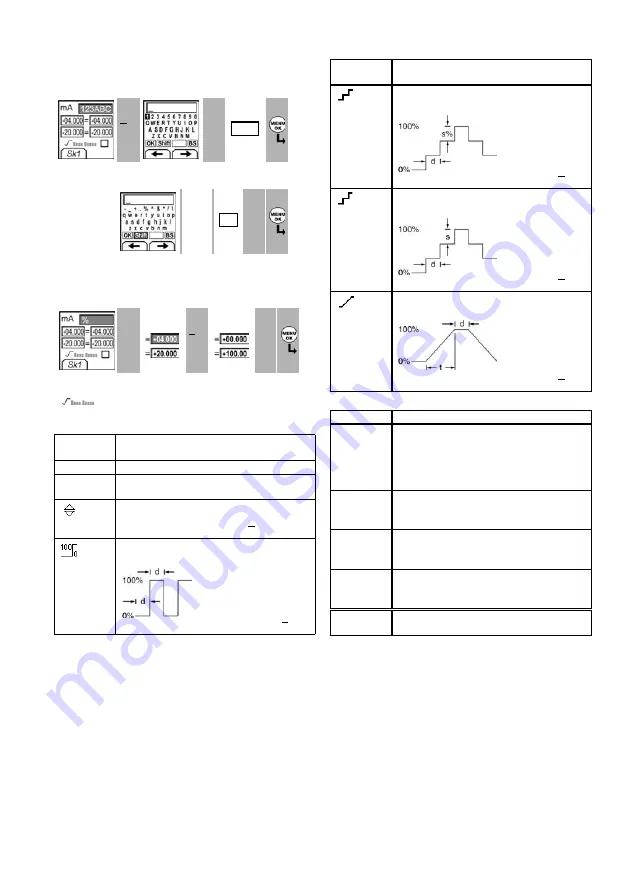
To start - Edit functions

Example 1) Set up a label for 

x:y Scaling

 = %.

Example 2) Set up values for 

x:y Scaling

 = 0 to 100%.

Table 5: 

(Part of table) 

Menu options - Settings (Output)

Table 5: (Part of table) Menu options - Settings (Output) 

Table 6: Additional data for Settings (Output):

Settings

x:y 

1

Edit


2

Edit

3


Sk1 = Edit

A3 - item [27]

Edit


...

Edit

4

5

%_


A3 - item [27]

Settings

x:y 

1

Settings

x:y

2

Edit

3

4


Sk1 = Edit

= Flow scaling

 (mA, pressure only) 

Options

(If applicable)

Description

... Units To select the temperature units (°C or °F).

... type To select an applicable thermocouple 

type (K, J, T ... )
To select and set up a value for the “Nudge” output. 
Example: 10°C increments.

Additional data: Select Settings 

(


)


To select and set up values for the “Span Check” 
output. Example output cycle: 

This cycle repeats 
automatically.

Additional data (

Table 6

): Select Settings 

(


)

Shift

OK

Options

(If applicable)

Description

 % Step

To select and set up values for the “% Step” output. 
Example output cycle:

Auto Repeat - Optional

Additional data (

Table 6

): Select Settings 

(


)

 ... Step

To select and set up values for the “Defined Step” 
output. Example output cycle:

Auto Repeat - Optional

Additional data (

Table 6

): Select Settings 

(


)


To select and set up values for the “Ramp” output. 
Example output cycle:

Auto Repeat - Optional

Additional data (

Table 6

): Select Settings 

(


)

Item

Value

Span Check

Low (0%)

Set the 0% value.

High (100%)

Set the 100% value.

Dwell (d)

Set the period (Hours:Minutes:Seconds) between 
each change in value.

% Step

Low (0%), High (100%), Dwell (d): As above.

Step Size (s) 
... %

Set the change in value for each step as a 
percentage of the full-scale range (High - Low).

Defined Step

Low (0%), High (100%), Dwell (d): As above.

Step Size (s)

Set the change in value for each step as a 
temperature or mV value.

Ramp

Low (0%), High (100%), Dwell (d): As above.

Travel (t)

Set the period (Hours:Minutes:Seconds) to go from 
the Low (0%) value to the High (100%) value.

Auto Repeat

If applicable, select this item to repeat a cycle 
continuously.

Summary of Contents for Druck DPI 821

Page 1: ...Thermocouple calibrator and Thermocouple loop calibrator User manual K346 GE Infrastructure Sensing 99 Washington Street Melrose MA 02176 Phone 781 665 1400 Toll Free 1 800 517 8431 Visit us at www TestEquipmentDepot com ...

Page 2: ...K346 Issue 2 A1 A2 DPI 822 A3 10 1 3 4 2 5 6 7 9 8 A2 A3 11 B1 12 14 15 13 20 21 22 25 17 18 26 19 27 16 23 24 B1 Customer service Visit our web site www gesensing com ...

Page 3: ...mes are trademarks of their respective companies Introduction The DPI 821 Thermocouple Calibrator and DPI 822 Thermocouple Loop Calibrator are part of the Druck DPI 800 series of hand held instruments The DPI 800 series uses Intelligent Digital Output Sensor IDOS technology to give instant plug and play functionality with a range of Universal Measurement Modules UMM Example the Universal Pressure ...

Page 4: ...Selects or accepts an item or value Selects or cancels a selection 7 Right hand soft key Selects the function above it on the display Item 25 Example Settings 8 Display Refer to A3 9 SENSOR PC Communications port Use to connect a Universal Measurement Module UMM or a RS232 cable 10 Thermocouple connector Refer to Operation 11 Connection point for some of the optional accessories Refer to the datas...

Page 5: ...applicable international temperature scale IPTS 68 or ITS 90 CJ To select the type of cold junction CJ compensation Automatic The instrument monitors the CJ temperature and applies the necessary CJ compensation Manual Measure the CJ temperature and set the applicable value The instrument uses this value to apply the necessary CJ compensation Additional data Manual Select Settings To select and set...

Page 6: ... type K J T To include maximum minimum and average values for the measurement task To select and set up a tare value for the measurement task a specified value or the reading on the display The instrument subtracts a positive tare value and adds a negative tare value Additional data Select Settings To select and set up a scale of values One local scale for each measurement task Maximum 5 Additiona...

Page 7: ... If applicable Description Step To select and set up values for the Step output Example output cycle Auto Repeat Optional Additional data Table 6 Select Settings Step To select and set up values for the Defined Step output Example output cycle Auto Repeat Optional Additional data Table 6 Select Settings To select and set up values for the Ramp output Example output cycle Auto Repeat Optional Addit...

Page 8: ...ure thermocouple values To measure the temperature or mV values of a thermocouple 1 Connect the instrument Figure 1 and if necessary adjust the Set Up Table 1 2 Select a T1 or mV input task from Select Task Table 2 3 and if necessary adjust the Settings Table 4 Figure 1 Example configuration To measure the temperature or mV values of a thermocouple Operation Change the output values When the outpu...

Page 9: ...mocouple Operation Transmitter calibration DPI 822 only To calibrate a transmitter 1 Connect the instrument Figure 3 4 and if necessary adjust the Set Up Table 1 2 Select the applicable calibration task from Select Task Table 2 3 and if necessary adjust the Settings Table 4 5 3 Supply the output values to the system Table 7 Figure 3 Example configuration Transmitter calibration with external loop ...

Page 10: ...losed in the top right hand corner 3 Supply the output values to the system Table 7 Example Nudge output a Use Edit to set a value less than the switch value b Use the buttons to change the value in small increments Example Ramp output a Set High and Low values that are applicable to the switch value Table 6 Then to get an accurate switch value set a long Travel period b Use Start Stop to start an...

Page 11: ...he Settings Table 4 5 2 If necessary do a zero correction Table 4 To measurepressure withanother operation Figure 8 use the same procedure Figure 8 Example configuration To measure pressure and temperature UPM Leak test To do a leak test on a pressure system Figure 7 1 Select an applicable leak test from Select Task Table 2 3 and if necessary adjust the Set Up Table 1 and the Settings Table 4 2 Se...

Page 12: ...the display shows the applicable instructions to complete the calibration When the calibration is complete select Calibration Due and set the new calibration date for the instrument Calibration Procedures mV input or output 1 Connect the instrument to the calibration equipment mV input Figure 1 mV output Figure 2 2 Let the equipment get to a stable temperature minimum 5 minutes since the last powe...

Page 13: ...re that the calibration is correct select the applicable mA input task Table 2 and apply these values mA 55 40 24 18 12 6 0 short circuit Then mA 0 6 12 18 24 40 55 5 Make sure that the error is in the specified limits Table 11 Table 11 mA input error limits Calibration Procedures IDOS UMM Refer to the user manual for the IDOS UMM When the calibration is complete the instrument automatically sets ...

Page 14: ...38 1832 150 1000 0 7 0 4 N IEC 584 454 4 270 20 1 8 1 0 N IEC 584 4 2372 20 1300 1 1 0 6 L DIN 43710 328 1652 200 900 0 6 0 3 U DIN 43710 328 212 200 100 0 9 0 5 U DIN 43710 212 1112 100 600 0 6 0 3 C 32 2732 0 1500 1 8 1 0 C 2732 3632 1500 2000 2 5 1 4 C 3632 4208 2000 2320 3 4 1 9 D 32 3092 0 1700 1 8 1 0 D 3092 3992 1700 2200 2 9 1 6 D 3992 4523 2200 2495 6 5 3 6 Cold Junction CJ error Maximum ...

Reviews: