background image

Measuring P and L Dimensions

D-1

March 2008

Introduction

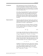
When programming the 

PIPE

 menu of the Model GS868’s 

User 

Program

, the 

path length

 (P) and the 

axial dimension

 (L) must be 

entered. These parameters are determined by measurements on the 
actual transducer installation, with P equal to the face-to-face distance 
between the transducers and L equal to the axial distance between the 
centers of the transducer faces.

The accuracy of the programmed P and L values is critical to precise 
flow rate measurements. If the factory supplies the flowcell for the 
system, the correct values will be included in the documentation 
supplied with the unit. For transducers installed on an existing pipe 
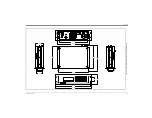
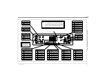
(see Figure D-1 on page D-2), P and L must be measured at the site. 
This appendix provides instructions for properly determining these 
dimensions.

Measuring P and L

Whenever possible, physically measure the face-to-face distance (P) 
and the axial distance (L) between the centers of the flat faces of the 
transducers. Refer to Figure D-1 on page D-2 for an illustration of the 
proper distances to measure in a typical installation.

In some situations only one of the required distances can be directly 
measured. When this happens, a knowledge of the installation angle 
(

θ

) of the transducers, permits the second distance to be calculated 

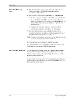
from Equation D-1 below:

(3-1)

As an example, assume that the transducer installation angle is known 
to be 45 ° and the L distance is measured to be 10.00 inches. Then, the 

P distance is calculated to be P = 10.00/0.707 = 14.14 inches.

With a Bias 90 ° transducer installation, it sometimes happens that the 

only known parameters are the transducer angle (

θ

) and the centerline 

distance between the transducer bodies (CL). In these cases, it is still 
possible to calculate P and L by combining Equation D-1 above with 
the additional Equation D-2 below (see Figure D-1 on page D-2):

(3-2)

Standard GE 90° transducers have the face offset from the centerline 

of the body by 0.6 inches. Thus, a pair of transducers has a total offset 
of 1.2 inches, as indicated in Equation D-2 above. For example, 
suppose that the transducer installation angle is 30° and CL is 
measured to be 12.00 inches. Then, P = 12.00 – 1.2 = 10.80 inches 
and L = 10.80 x 0.866 = 9.35 inches.

θ

cos

L

P

---

=

P

CL

1.2

=

Summary of Contents for DigitalFlow GS868

Page 1: ...GE Sensing Inspection Technologies DigitalFlow GS868 Panametrics Steam Ultrasonic Mass Flowmeter Startup Guide 1 and 2 Channel...

Page 2: ...ametrics Steam Ultrasonic Mass Flowmeter Startup Guide 1 and 2 Channel 910 190UD1 March 2008 The DigitalFlow GS868 is a GE Panametrics product GE Panametrics has joined other GE high technology busine...

Page 3: ...and warranties arising from course of dealing or usage or trade Return Policy If a GE Sensing Inc instrument malfunctions within the warranty period the following procedure must be completed 1 Notify...

Page 4: ...the Serial Port 1 10 Wiring an Alarms Option Card 1 14 Wiring a 0 4 20 mA Analog Inputs Option Card 1 15 Wiring a Totalizer Frequency Outputs Option Card 1 16 Wiring an RTD Inputs Option Card 1 17 Wi...

Page 5: ...lectrical 4 2 Operational 4 4 Transducer 4 4 Flowcell 4 5 Appendix A CE Mark Compliance Introduction A 1 Wiring A 1 External Grounding A 1 Appendix B Data Records Option Cards Installed B 1 Initial Se...

Page 6: ...Chapter 1...

Page 7: ...Introduction 1 1 Unpacking 1 1 Site Considerations 1 2 Installing a Flowcell 1 3 Installing Temperature and Pressure Transmitters 1 5 Mounting the GS868 Electronic Console 1 6 Making the Electrical Co...

Page 8: ...rdous In such cases the importance of proper safety practices cannot be overemphasized Be sure to follow all applicable local safety codes and regulations for installing electrical equipment and worki...

Page 9: ...with unlimited access as the flowcell for example a long stretch of pipe that is above ground However if the flowcell is mounted on an underground pipe dig a pit around the pipe to facilitate installa...

Page 10: ...cables and connections from the weather and corrosive atmospheres Note When using non GE cables to connect the flowmeter transducers to the Model GS868 electronics console the cables must have electr...

Page 11: ...March 2008 1 4 Installation Figure 1 1 A Typical Model GS868 System Transducer Flowcell Temperature Transmitter Pressure Transmitter Preamp Transducer Electronics Console STEAM FLOW...

Page 12: ...good choice for measuring the temperature Typically a 1 2 or 3 4 NPT female threaded port is used to mount the transmitters on the flowcell If the pipeline is insulated the coupling may need to be ex...

Page 13: ...onnections to the Model GS868 flowmeter Refer to Figure 1 10 on page 1 20 for a complete wiring diagram of the unit IMPORTANT For meters supplied in one of the optional enclosure styles refer to Appen...

Page 14: ...connect the meter only to the specified line voltage Note For compliance with the European Union s Low Voltage Directive 73 23 EEC this unit requires an external power disconnect device such as a swi...

Page 15: ...connection located on the side panel of the inclosure see Figure 1 3 below IMPORTANT The incoming ground lead must be connected to the internal ground connection 4 Connect the neutral or line lead or...

Page 16: ...uivalent cables connect both transducers to the preamplifier Caution As part of maintaining the FM CSA environmental rating NEMA TYPE 4 on the remote preamplifier thread sealant is required on all con...

Page 17: ...terface for connecting the Model GS868 flowmeter to a printer an ANSI terminal or a personal computer The RS232 serial interface is wired as Data Terminal Equipment DTE and the signals available at th...

Page 18: ...er to the unit and remove the cover 2 Install the required cable clamp in the chosen conduit hole on the side of the electronics enclosure 3 Feed one end of the cable through the conduit hole wire it...

Page 19: ...o Chapter 6 of the Programming Manual Wiring the MODBUS TCP Interface Customers can also use a modified GS868 that provides a MODBUS TCP interface to communicate to an internal network An optional MOD...

Page 20: ...stalled depending on the option ordered by the customer No connections are made to J8 J9 pins 7 and 9 under normal operation If it is desired to reset the network board to factory defaults 1 Connect a...

Page 21: ...up an alarm relay it may be wired for either conventional or fail safe operation In fail safe mode the alarm relay is constantly energized except when it is triggered or a power failure or other inter...

Page 22: ...enter programming data during operation of the meter it will be necessary to know which input is assigned to which process parameter This information should have been entered in Appendix B Data Recor...

Page 23: ...n the Service Manual for the appropriate procedures Wiring a Totalizer Frequency Outputs Option Card The Model GS868 can accommodate up to four totalizer frequency outputs option cards Each totalizer...

Page 24: ...through one of the conduit holes on the bottom of the electronic console Wire this terminal block in accordance with the pin number assignments shown in Figure 1 10 on page 1 20 Wiring a 0 4 20 mA Ana...

Page 25: ...3 1 54 39 1 65 42 2 26 57 1 50 38 1 77 45 1 30 33 2 26 57 1 20 30 1 2 Conduit Plate 11 37 289 3 4 Conduit Plate 2 87 7 00 2 69 68 0 75 19 0 38 10 4 Places 0 13 3 4 Places 0 88 22 10 Places 1 10 28 6 P...

Page 26: ...March 2008 Installation 1 20 G N L2 L1 G Figure 1 10 Model GS868 Electronics Console Wiring ref dwg 702 213 sht 1 of 2...

Page 27: ...PRESSURE AND TEMPERATURE INPUTS TEMPERATURE INPUT GS868 JUMPER WIRE NOT SUPPLIED JUMPER WIRE NOT SUPPLIED PREAMPLIFIER CO NS OL E UP DN DN XD CR PAN AME TRIC S PRE 868 S N UP SUPPLIED BY GE 10 FOOT C...

Page 28: ...Chapter 2...

Page 29: ...Initial Setup Introduction 2 1 Navigating Through the User Program 2 1 Accessing the User Program 2 2 Activating a Channel 2 3 Entering System Data for a Channel 2 4 Entering Pipe Data 2 7...

Page 30: ...easurement method for a 2 Channel meter it is also used to activate a channel SYSTM prompts the user to enter the required system data PIPE prompts the user to enter the required pipe parameters As a...

Page 31: ...YSTM and PIPE are discussed in this manual Refer to the Programming Manual for information on the other submenus Note In this manual only the programming of Channel 1 will be described To program Chan...

Page 32: ...s 3 Press F1 to select Skan mode or F2 to select Skan Measure mode The meter will exit the ACTIV submenu and return to the channel menu screen As indicated in the above prompt the Model GS868 flowmete...

Page 33: ...ons and definitions of all the available pressure units are shown in Table 2 1 below The choices shown on the option bar are determined by the selections made at the previous SYSTEM UNITS prompt a If...

Page 34: ...of this submenu 1 and 2 Channel Meters 1 At the Equation prompt press F1 to display the measurement data in standard volumetric units or press F2 to display the measurement data in actual volumetric u...

Page 35: ...l point in the totalized flow display 7 If the Static Density prompt in the ADVAN submenu SETUP menu is set to NO the GS868 returns to the initial User Program screen Otherwise proceed as follows a Us...

Page 36: ...ime Delay Tw value supplied by the factory Press ENT The meter will only accept values from 0 to 1000 sec Note Tw is the time required for the transducer signal to travel through the transducer and it...

Page 37: ...signal path length P and the transducer signal axial length L based on the exact transducer configuration used for the application These values are engraved on the flowcell and or are included in the...

Page 38: ...2 channel GS868 and then press F1 NO at the SAVE prompt Any programming changes will be discarded and you will be returned to the data display To leave the User Program and return to measurement mode...

Page 39: ...F F4 SCF F2 English Metric F4 3 F3 2 F2 1 F1 0 VOL DECIMAL DIGITS TOTALIZER UNITS F1 F2 ACM KACM F3 F2 KACF F1 ACF F3 F4 F1 SCM KSCM F2 F1 KSCF F4 SCF F2 English Metric F4 3 F3 2 F2 1 F1 0 VOL DECIMAL...

Page 40: ...Chapter 3...

Page 41: ...Operation Introduction 3 1 Powering Up 3 2 Using the Display 3 3 Taking Measurements 3 5...

Page 42: ...king Measurements Note All inputs and outputs of the Model GS868 are calibrated at the factory prior to shipment If it becomes necessary to recalibrate any of the inputs and or outputs see Chapter 1 C...

Page 43: ...e of the display window Note If the Model GS868 fails any of the internal checks try disconnecting the power and then re powering the unit If the Model GS868 continues to fail any of the internal chec...

Page 44: ...a blank option bar See the Programming Manual for detailed instructions on using the keypad As shown in Figure 3 2 on page 3 3 each pane of the display screen is divided into the following three gener...

Page 45: ...mbol indicates that the Model GS868 is currently totalizing data The middle portion of the screen pane is the prompt area This area displays data graphs and logs in measurement mode and menu prompts i...

Page 46: ...completion of the internal checks As an example the display shows the measured velocity in ft sec for Channel 1 The following screen appears after selection of the channel mode display option for a 2...

Page 47: ...68 can be set up to display the desired channel option for a 2 Channel meter and the desired measurement parameter To utilize the more advanced display capabilities of the Model GS868 refer to the Pro...

Page 48: ...none Ch1 Std Volumetric VOL_U Ch1 Rev Mass Totals MTOT_U Ch1 Sound Speed ft s or m s Ch1 Fwd Totals TOT_U Ch1 Mass Tot Digits none Ch1 Density see note Ch1 Rev Totals TOT_U Ch1 Timer sec Ch1 Temperatu...

Page 49: ...Chapter 4...

Page 50: ...Specifications General 4 1 Electrical 4 2 Operational 4 4 Transducer 4 4 Flowcell 4 5...

Page 51: ...o 75 C Flow Accuracy of Reading 1 to 2 of reading typical Note Accuracy depends on pipe size and whether measurement is 1 path or 2 path Accuracy to 0 5 of reading may be achievable with process calib...

Page 52: ...on Category II Pollution Degree 2 and PED 97 23 EC for DN 25 Input Output Specifications Keypad 39 key membrane keypad with tactile feedback Display Both single and dual channel models have a software...

Page 53: ...o 3 Totalizer Frequency Output Boards each with four outputs per board 10 kHz max All boards allow software selectable functioning in two modes Totalizer Mode one pulse per defined unit of parameter e...

Page 54: ...programmable for setting up log units update interval start and stop times Memory capacity for more than 43 000 flow data points in a linear or circular log Display Functions Liquid crystal graphic d...

Page 55: ...lowmeter are divided into the following categories Spoolpiece Process Connections Flanged typical welded optional Transducer Connections 1 5 in 300 lb flange for T9 transducer 1 5 in 150 2 500 lb flan...

Page 56: ...Appendix A...

Page 57: ...CE Mark Compliance Introduction A 1 Wiring A 1 External Grounding A 1...

Page 58: ...sure and the transducer fixture must each have an external ground wire attached Note If the Model GS868 is wired as described in this appendix the unit will comply with the EMC Directive 89 336 EEC Ta...

Page 59: ...Appendix B...

Page 60: ...Data Records Option Cards Installed B 1 Initial Setup Data B 2...

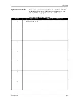
Page 61: ...installed in one of the Model GS868 s expansion slots record the type of card and any additional setup information in the appropriate row of Table B 1 below Table B 1 Option Cards Installed Slot Type...

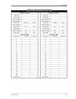
Page 62: ...Label Site Message Chan 1 Message System Units English Metric Chan 2 Label Pressure Units Chan 2 Message Stopwatch Total Auto Manual 1 Channel and 2 Channel Channel 1 Channel 2 if applicable Gas Equat...

Page 63: ...eam Other Other Sndspd Other Sndspd Mass Flow No Yes Mass Flow No Yes Fluid Density Fluid Density Multi K factors Off On Multi K factors Off On Edit Table No Yes Edit Table No Yes K factor Table K fac...

Page 64: ...Appendix C...

Page 65: ...Optional Enclosures Introduction C 1 Rack Mount Enclosure C 1 Rack Mount Wiring C 1 Rack Mount Front Panel C 2...

Page 66: ...into the rack proceed to the next section for instructions on wiring the meter Rack Mount Wiring The rack mount Model GS868 requires exactly the same electrical connections as the standard version Ho...

Page 67: ...any installed option cards using the same procedures described in Chapter 1 Installation of this manual and the pin assignments shown in Figure C 2 on page C 4 Note The pins on the option card connect...

Page 68: ...Enclosures C 3 GS868 19 00 483 18 25 464 2 25 5 22 11 37 11 82 13 13 4 19 106 15 70 399 3 31 84 14 83 377 16 99 432 A OUT ALARMS A IN RTD IN 289 300 333 57 133 Figure C 1 Model GS868 Rack Mount Enclos...

Page 69: ...put D SIG Output D RTN Output C SIG Output C RTN 7 8 6 4 5 2 3 1 7 8 6 4 5 2 3 1 0 4 20 mA ANALOG OUTPUTS Pin Pin Description Output A Normally Open NO Output D Normally Open NO Output C Common C Outp...

Page 70: ...L HELP P V I H CLR O DISP Q PROG W J EXIT 6 N U 3 0 S 1 Y 4 L R X K ENT T 2 Z 5 M B A C G 9 7 E D 8 F Handle Mounting Holes Mounting Holes Main Keypad Console Keys Function Keys LCD Display Handle Fig...

Page 71: ...Appendix D...

Page 72: ...Measuring P and L Dimensions Introduction D 1 Measuring P and L D 1...

Page 73: ...e D 2 for an illustration of the proper distances to measure in a typical installation In some situations only one of the required distances can be directly measured When this happens a knowledge of t...

Page 74: ...March 2008 D 2 Measuring P and L Dimensions Figure D 1 Top View of Transducer Installations Pipe O D L P Pipe Thickness L P CL 180 Installation Bias 90 Installation...

Page 75: ...Message 2 5 Connecting See Part Name Connectors Electrical 1 6 D Display Channel Mode Options 3 5 Components 3 3 Data 3 2 Locator Bar 3 3 Locator Bar Symbols 3 4 Measurement Mode 3 2 Metric or English...

Page 76: ...etup Information Table B 1 Totalizer Frequency Outputs 1 16 P Parameter Options 3 6 Password 2 2 Path Length 2 8 D 1 Pipe OD 2 7 Available Units 2 7 Pipe OD Programming 2 7 PIPE Submenu 2 7 Pipe Wall...

Page 77: ...3 RTD 1 5 Terminal Block Analog Outputs I O 1 10 Power TB1 1 7 Serial Port RS232 1 10 Transducers CH1 CH2 1 9 Time Delay 2 7 Totalizer Frequency Option Card Connecting 1 16 Transducer Number 2 7 Tran...

Page 78: ...e following standards EN 61326 1998 Class A Annex A Continuous Unmonitored Operation EN 61010 1 1993 A2 1995 Overvoltage Category II Pollution Degree 2 following the provisions of the 89 336 EEC EMC D...

Page 79: ...Continuous Unmonitored Operation EN 61010 1 1993 A2 1995 Overvoltage Category II Pollution Degree 2 suivant les r gles de la Directive de Compatibilit Electromagn tique 89 336 EEC et de la Directive B...

Page 80: ...erf llen EN 61326 1998 Class A Annex A Continuous Unmonitored Operation EN 61010 1 1993 A2 1995 Overvoltage Category II Pollution Degree 2 gem den Europ ischen Richtlinien Niederspannungsrichtlinie Nr...

Page 81: ...USA 1100 Technology Park Drive Billerica MA 01821 4111 Web www gesensing com Ireland Sensing House Shannon Free Zone East Shannon County Clare Ireland...

Reviews: