


9
Temperature Selector Switch
The rotary temperature selector switch, one of the
controls on the model DBL333, allows the customer
to select different temperature settings for drying.
The switch contains a 3K ohm resistor on the electric
model and a 2.4K ohm resistor on the gas model.
On the “Medium” setting, the selector switch
activates a control thermostat bias heater, which is
in series with the resistor on the switch. To check
the switch, disconnect power, remove the wires from
the switch and check
for continuity. With the
switch set on “Regular”
setting, there should be
continuity only between
terminals 1 and 2. On
the “Medium” setting,
there should be
continuity only between
terminals 3 and 4. On a “Fluff” setting, there should
be no continuity between either set of terminals.
Resistor
3
5
2
1
4
Dryer Controls
To access the dryer controls, disconnect power and
remove the four Phillips screws at the top of the
switch trim. Grasp the trim at the top and pull forward.
Three tabs at the bottom fit into slots on the top panel.
START
HIGH
MEDIUM
FLUFF
MORE DRY
MORE DRY
= PREFERRED REGU
LAR SETTING
80 MIN
70
60
50
40
30
20
LESS DRY
LESS DRY
COOL
DOWN
AUTOMATIC
COTTONS
AUTOMATIC
PERMANEN
T
PRESS
TIMED DRY
3 Cycle Automatic
Heavy Duty La
rge Capacity
START
TEMPERATU
RE
Start Switch
The start switch energizes the start windings on the
drive motor. It is a momentary contact, rotary switch.
To test the switch, remove the wires and check for
continuity between the switch terminals. There
should be continuity only while turning the switch
clockwise. Once released, the terminals should read
open. Should the switch need to be replaced, turn
the switch clockwise (as viewed from the back) to
release it from the switch trim.
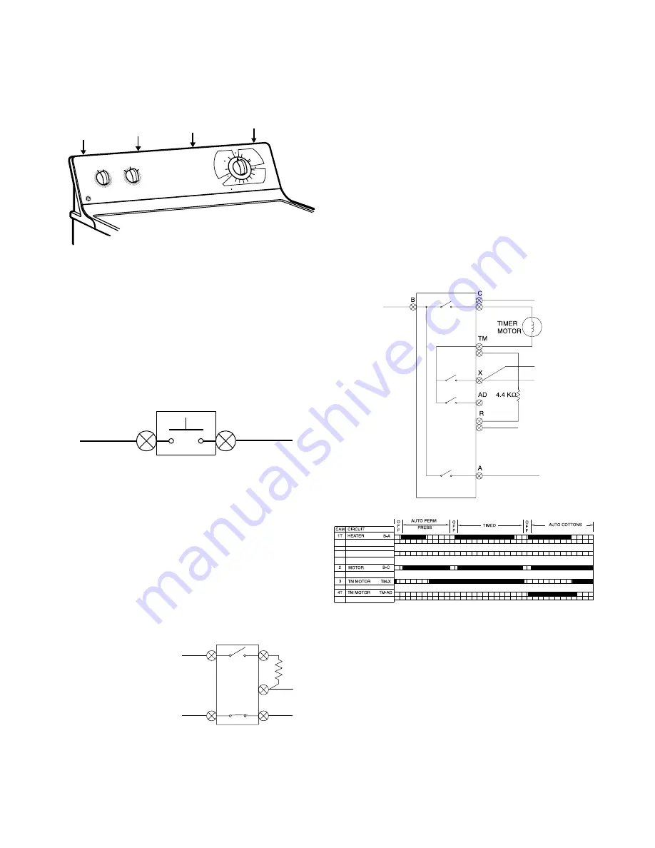
Timer
The timer is an electromechanical control with a 120v
drive motor. Depending upon the model, the timer
will control cycles for timed fluff (no heat), timed dry,
automatic cottons and/or automatic permanent
press. On a timed cycle, the timer motor receives
120 volts continuously for the number of minutes
selected for the cycle. When an automatic cycle is
chosen, the time will vary based of the quantity of
clothes and their moisture content. When the heat
source is on, the timer motor does not receive power.
When the clothes warm and the control thermostat
is satisfied, the heat is turned off and voltage is then
supplied to the timer motor. When the thermostat
cools, the heat is again turned on and the timer stops.
As the clothes dry, the control thermostat reaches
temperature faster and the timer motor receives
power more often until the end of cycle is reached.
To diagnose the timer, use the timer bar chart located
on the mini manual behind the switch trim. Rotate
the timer to a point in the particular cycle you want
to check. Find the appropriate location the timer
pointer is set in the cycles across the first column.
Read vertically down the chart from that point. At
each point you cross a shaded row, the contacts
listed at the left on the same row should have
continuity. Note the shaded areas are proportional
to the total time, so take several continuity
measurements at different points within the cycle
before determining the timer needs replacement.
Timer Bar Chart
Summary of Contents for DBL333
Page 17: ...15 DBL333E ...
Page 18: ...16 DBL333G ...
Page 19: ...17 DCL333E ...
Page 20: ...18 DCL333G ...
Page 21: ...19 DVL223E ...
Page 22: ...20 DVL223G ...
Page 28: ...26 Model DBL333EY0WW shown ...
Page 30: ...28 Model DBL333EY0WW shown ...
Page 32: ...30 Model DBL333EY0WW shown ...
Page 34: ...32 Model DBL333EY0WW shown ...
Page 36: ...34 Model DBL333GY0AAshown ...


