background image

CS300

———————   Half controlled power supply for inverter DC-Link   ————————

11

Chapter 2 - COMPONENT IDENTIFICATION AND SPECIFICATION

2.1  GENERAL DESCRIPTION

CS300 is a half-controlled three phase AC/DC converter for supplying DC link voltage to a series of AC Drives,
with C and D terminals parallel connected.

The precharge of the drive capacitors (time setting set via dip-switches) is done by partializing the mains
voltage via a thyristors bridge. A diagnostic circuit allows  detection of a mains power supply dip for
system use.

NOTE!

The direct parallel connection of the outputs (U2,V2,W2 terminals) of two or more inverters
is not possible !

2.2  POWER SUPPLY

CS300 converter can be connected to the three phase power supply having the following characteristics:

400V-15%

   up to

480+10%

50 or 60 Hz

(Dip-switch selectable)

The maximum input power of the internal switching power supply is 100W, and the supplied voltages are:

+/-15V 500mA

Control card

+24 V 2A

Fan power supply (if present) and auxiliary functions (regulator

terminals power supply)

2.3  DESCRIPTION OF POWER TERMINALS

Terminals

Function

U, V, W

Power supply via AC mains, 3Ph (400V –15% up to 480V +10%)

C

Positive

terminal to be connected to the inverter DC-LINK

D

Negative

terminal to be connected to the inverter DC-LINK

Supply for internal fan (only for 1050A size and higher)
(1Ph, 230V ± 15%)

cs010

U3, V3

Summary of Contents for CS300 User's guide

Page 1: ...GEH 6639 Draft GE Industrial Systems CS300 Half Controlled Power Supply for Inverter DC Link User s Guide ...

Page 2: ...uld be referred to GE Industrial Systems Salem Virginia USA This document contains proprietary information of General Electric Company USA and is furnished to its customer solely to assist that customer in the installation testing operation and or maintenance of the equip ment described This document shall not be reproduced in whole or in part nor shall its contents be disclosed to any third party...

Page 3: ...es and of the damages which could be caused by the non obser vance of such indications depends on the different conditions Anyway the instructions given below should always be followed with the highest attention Attire l attention sur les modes d utilization et les procédés et conditions d exploitation qui en cas d inobservation pourraient entraîner la détérioration ou la destruction des appareils...

Page 4: ...GEH 6639 INSTRUCTION MANUAL 4 ...

Page 5: ...CTION 14 2 6 1 Output Rated Currents for the Two Functioning Classes 14 2 6 2 Drive DC Current DC Link Circuit 15 CHAPTER 3 SELECTION OF THE CS300 CONVERTER 16 3 1 DIP SWITCHES AND JUMPER 16 3 2 USE OF S1 SWITCH 16 3 3 USE OF S2 SWITCH 18 3 4 USE OF S3 SWITCH 18 3 5 USE OF S4 AND S5 DIP SWITCH 19 3 6 USE OF CV JUMPER 19 CHAPTER 4 CONTROL DESCRIPTION 20 4 1 OK RELAY 20 4 2 PRECHARGE ENABLING CONTRO...

Page 6: ...GEH 6639 INSTRUCTION MANUAL 6 ...

Page 7: ...avoir verifié que la machine ait été produit avec les même dispositifs de sécurité demandés par la réglementation 89 392 EEC concernant le secteur de l industrie Les systèmes provoquent des mouvements mécaniques L utilisateur est responsable de la sécurité concernant les mouvements mécaniques Les dispositifs de sécurité prévues par l usine et les limitations operationelles ne doivent être dépassés...

Page 8: ...eux accidents ou même la mort Les drives à fréquence variable sont des dispositifs électriques utilisés dans des installations industriels Une partie des drives sont sous tension pendant l operation L installation électrique et l ouverture des drives devrait être executé uniquement par du personel qualifié De mauvaises installations de moteurs ou de drives peuvent provoquer des dommages materiels ...

Page 9: ...ument de serrage specifié par le producteur du connecteur Ne pas exécuter un test megger entre les bornes du drive ou entre les bornes du circuit de contrôle Étant donné que la température ambiante influe sur la vie et la fiabilité du drive on ne devrait pas installer le drive dans des places ou la temperature permise est dépassée Laisser le capot de ventilation en place pour températures de 104 F...

Page 10: ...GEH 6639 INSTRUCTION MANUAL 10 ...

Page 11: ...2 V2 W2 terminals of two or more inverters is not possible 2 2 POWER SUPPLY CS300 converter can be connected to the three phase power supply having the following characteristics 400V 15 up to 480 10 50 or 60 Hz Dip switch selectable The maximum input power of the internal switching power supply is 100W and the supplied voltages are 15V 500mA Control card 24 V 2A Fan power supply if present and aux...

Page 12: ...upply of the ML and MLP signals 35V max 52 Common Ground of the precharge enable control 70 72 OK Relay max 250V 1A AC11 cs020 2 5 PROTECTIONS 2 5 1 Internal Protection Components Converter Designation Varistors 6KCS3185 480 6KCS3280 480 6KCS3420 480 575 V 220 J 6KCS3650 480 Ø 20 mm 6KCS310H 480 6KCS315H 480 cs025 V1 V2 V3 2 5 2 Internal Fuses Converter Designation Fuses Designation Fuses for Fuse...

Page 13: ...ABLADE A 1 3 G3MUEF1 1000A 660V SKF4G76 SKF4G76 B 1 1 1 1 1 S3üF1 110 1000A 660V SKF4H03 A70P1000 FWP1000 SKS7812 cs041 USA Type 170M5466 1000A 700V G3MUEF1 1000A 660V 6KCS310H 480 6KCS315H 480 Europe 6KCS3185 480 6KCS3280 480 6KCS3420 480 6KCS3650 480 Converter Ref Pieces Ref A External fuses for the input side power supply bridge B External fuses for the DC link output 1 Fuses integrated in the ...

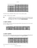
Page 14: ...ased on a common unit the direct current of the intermediate circuit which as for the inverters is not mentioned into the product instruction manual and has therefore to be calculated Furthermore the confrontation between the two foreseen functioning classes has to be homogeneous IEC 146 class 1 and 2 2 6 1 Output Rated Currents for the Two Functioning Classes DC link current Terminals C D IEC 146...

Page 15: ...75 4090 90 0 946 191 19 260 02 315 4090 4110 110 0 947 233 43 317 46 350 4110 4132 132 0 951 278 94 379 35 450 4132 4160 160 0 955 336 69 457 90 500 4160 4250 200 0 958 419 54 570 58 630 4250 4250 250 0 96 523 33 711 74 800 4250 4315 315 0 963 657 35 893 99 1000 4315 355 0 963 740 82 1007 52 400 0 965 833 00 1132 88 cs070 AV300 The following table states the direct current values of the dc link ac...

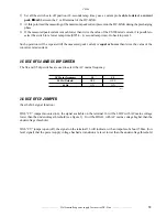
Page 16: ...sequence once the voltage is restored The disadvantage of such function is obviously the presence of a high current inside the CS300 once the voltage is restored For this reason it is necessary to take appropriate countermeasures by checking the decreasing slope of the DC LINK voltage during the mains dip Therefore knowing the value of the connected capacitors and the maximum current supplied by t...

Page 17: ... formula e L V I t P M α ω from which IP 572 3A It is obvious that considering a 70V discharge of the DC LINK 3 mS mains dip the current is too high for the converter As a consequence it is necessary to consider a lower voltage reduction corresponding to a shorter mains dip Therefore with a voltage reduction of 35V 1 5 mS mains dip the new value will be IP 286 1 A Such value meets the needing of b...

Page 18: ...quence will be executed again default configuration 3 3 USE OF S2 SWITCH Via the S2 switch it is possible to select the undervoltage threshold which depends on the AC main voltage of the converter Dip S2 4 not used Power supply voltage S2 1 S2 2 S2 3 Threshold of the PS drop 460V 10 480V 10 Default ON OFF OFF 370 Vdc 400V 15 OFF ON OFF 300 Vdc 230 10 10 OFF OFF ON 180 Vdc cs090 3 4 USE OF S3 SWITC...

Page 19: ... till the measured peak current is equal or lower than twice the value of the converter rated current 3 5 USE OF S4 AND S5 DIP SWITCH The S4 and S5 dip switches are used to select the AC mains frequency AC Mains frequency S4 S5 50 Hz Default OFF OFF 60 Hz ON ON cs110 3 6 USE OF CV JUMPER See the ML signal function With CV jumper mounted on the signal available on the terminal 36 will be LOW with A...

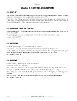
Page 20: ...e on the terminal strip common on terminal 52 4 3 MLP SIGNAL The MLP signal is a digital output available on the terminal 32 This signal is a sum of the undervoltage threshold via S2 1 3 set and the precharging phase It will be LOW with a 0 5mS delay after the undervoltage threshold is reached The digital output will be again HIGH at the end of the precharging phase This sequence is repeated at ev...

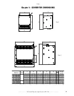
Page 21: ... 61 270 14 73 375 10 70 275 M6 36 6 18 6KCS3280 480 12 22 311 15 25 388 10 61 270 14 73 375 10 70 275 M6 57 3 26 6KCS3420 480 12 22 311 15 25 388 10 61 270 14 73 375 10 70 275 M6 66 1 30 6KCS3650 480 12 22 311 15 25 388 10 61 270 14 73 375 10 70 275 M6 68 3 31 6KCS310H 480 20 63 525 21 77 554 13 48 343 7 86 200 19 65 500 M6 138 8 63 6KCS315H 480 21 65 551 26 96 686 14 93 380 7 86 200 20 67 526 M8 ...

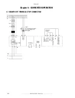
Page 22: ...3 N PE 5 1 3 2 4 6 5 F1 F2 1 2 3 4 6 70 72 OK Relay U V W PE U3 V3 C D D Q2 PE PE 35 37 34 33 32 36 52 23 PRECHARGE COMMAND From 1050 size Digital output Note Fan with external supply only from 1050A size and higher MLP ML Precharge enable Common MLP ML GND 24 Common Precharge enable 24V Power supply of the ML and MLP ...

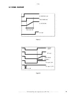
Page 23: ...y for inverter DC Link 23 6 2 SIGNAL DIAGRAM AC CONTACTOR U V W PRECHARGE ENABLE DC LINK VOLTAGE PRECHARGE TIME OK RELAY Figure A AC POWER SUPPLY MLP signal TYRISTOR FIRING PRECHARGE ML signal CV ON ML signal CV OFF 150 ms MIN Figure B ...

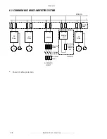
Page 24: ...ULTI INVERTER SYSTEM M M M E E D C D C D C D C D _ C AC Drive AC Drive CS300 Braking unit External braking resistor Rbr AC Drive External fuses AC mains choke AC mains contactor AC MAINS INPUT OPTION External fuses DC BUS Fuses for cables protection ...

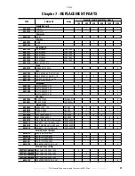
Page 25: ... EC 3 SCR filters 6KS7S58 RC SCR FILTER 18ohm50W 3 6KS8S61 RC SCR FILTER 1mF 850Vac 3 Internal fuses 6KS8B28 FUSES 5X20 T20 1A 250V 1 1 1 1 1 1 6KS8B19 FUSES 6 3X32 4A 500V 1 1 1 1 1 1 6KS8B30 FUSES 6 3X32 1 6A 500V 1 1 6KS820B FAST FUSES 6 3X32 16A 500V 3 3 3 3 6KS821B FAST FUSES 6 3X32 25A 500V 3 3 6KS827B FUS PWR GOULD for Europe only 1000A 660V 3 6KF4G76 G3MUEF1 JM for Europe only 1000A 660V 6...

Page 26: ...tion or 18 months after shipment from the Company whichever occurs first However the guarantee will not apply in the following cases even if the guarantee term has not expired 1 Damage was caused by incorrect use or inappro priate repair or modification 2 The product was used in an environment outside the standard specified range 3 Damage was caused by dropping the product after purchase or occurr...

Page 27: ...CS300 Half controlled power supply for inverter DC Link 27 Notes ...

Page 28: ...GE Industrial Systems 1 540 387 7000 www GEindustrial com General Electric Company 1501 Roanoke Blvd Salem VA 24153 6492 USA GEH 6639 Draft 010119 SIEI ...

Reviews: