background image

27

8.

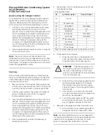
Press and hold the SET and UP button for 5 seconds 
to cancel regeneration, and cycle the control back to 
the service position. 

9.

Start another regeneration. Advance the controller to 
the brine refill position (C8) to prime the line between 
the regenerant tank and the valve (conditioner only).

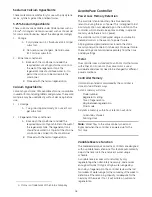
A. Slowly open the main water supply valve 

again to the fully open position. Be sure not to 
open too rapidly, as that would push the 
media out of the media tank.

Note:

As you advance through each cycle, there will be a 

slight delay before you can advance to the next cycle. 
There will be a pause after the brine draw and slow rinse 
cycles (system pause). This cycle allows the water/air 
pressure to equalize on each side of the valve discs.

B. With the water supply completely open, when 

you arrive at the brine tank refill cycle, the 
controller will direct water down through the 
line and into the tank. Watch the bottom of 
the tank until all air bubbles have been 
purged from the line and the water level is 
rising.

C. Let the water flow down the line to the tank 

only until the rising water is vis able.

D. Simultaneously press and release the SET and 

UP buttons to advance to the Brine Make-up 
cycle. After the Brine Make-up cycle is 
reached, press the SET and UP buttons to 
advance to the Brine Draw/Slow Rinse cycle.

10. Draw water from the regenerant tank.

A. With the controller in this position, check to 

see that the water in the regenerant tank is 
being drawn out of the tank. The water level in 
the tank should recede very slowly.

B. If the water in the regenerant tank does not 

recede, or goes up, refer to the 
Troubleshooting section.

11. If the water level is receding from the regenerant 

tank, wait for the tank check valve to stop the water 
flow. Press the SET and UP buttons to advance the 
controller back to the treated water position.

12. Finally, turn on a faucet plumbed after the water 

conditioner. Run the faucet until the water runs clear.

The Water Conditioning System is Now 

Fully Operational.

Summary of Contents for AvantaPure

Page 1: ...Operation Manual Models 269 Upflow Conditioner System AvantaPure Professional Series Water Treatment System by GE ...

Page 2: ...e Connection 15 Electrical Connection 15 System Operation 16 Cycle Water Flows 16 Valve Camshaft 17 Valve Operation 17 Injector Instructions 17 Disinfection of Water Conditioners 17 AvantaPure Controller 18 Display Icons 19 Keypad Button 19 Things You Might Need to Know 20 Programming Overview 20 Level I Programming 21 Viewing and Changing the Model Number 22 Level II Programming 23 Level lll Cycl...

Page 3: ...ater softeners shall have a rated salt efficiency of not less that 3350 grains of total hardness exchanged per pound of salt based on NaCl equivalency 477 grams of total hardness exchanged per kilogram of salt and shall not deliver more salt than its listed rating The rated efficiency of the water softener the salt dosage at that efficiency the capacity at that salt dosage and that of the efficien...

Page 4: ...ter that is supplied The power outlet must be grounded To disconnect power unplug the AC adapter from its power source Mechanical Do not use petroleum based lubricants such as vaseline oils or hydrocarbon based lubricants Use only 100 silicone lubricants All plastic connections should be hand tightened Teflon tape may be used on connections that do not use an O ring seal Do not use pliers or pipe ...

Page 5: ...microbiologically unsafe or of unknown quality When filling media tank do not open water valve completely Fill tank slowly to prevent media from exiting the tank When installing the water connection bypass or manifold connect to the plumbing system first Allow heated parts to cool and cemented parts to set before installing any plastic parts Do not get primer or solvent on O rings nuts or the valv...

Page 6: ...et Drain Inlet Backwash Injector Screen Camshaft Drain Control Filter Control Module Mount One Piece Valve Disc Spring Motor Optical Sensor LBS PM MIN KG x100 LCD Display Manual Regen Button Down Button Set Button Up Button For Future Use Turbine Input or Dry Contact Signal Input Main Motor Optical Sensor Connection AC Adapter low voltage Input Chlorine Generator Outlet ...

Page 7: ... 25 ft3 1 5 ft3 Recharge Salt Tank Size 15 x 40 15 x 40 15 x 40 Salt Storage 240 lbs 240 lbs 240 lbs Drain Water Rate 2 7 gpm 2 7 gpm 2 7 gpm Service Connection Size 1 NPT 1 NPT 1 NPT Drain Connection Size 3 4 NPT 3 4 NPT 3 4 NPT Recharge Brine Connection Size 3 8 NPT 3 8 NPT 3 8 NPT Typical Installation Space Requirements 26 W x 20 D x 46 H 26 W x 20 D x 50 H 26 W x 20 D x 60 H Shipping Weight 10...

Page 8: ...s recommended When the water conditioning system is installed outdoors several items must be considered Moisture The valve and control are rated for NEMA 3 locations Falling water should not affect performance The system is not designed to withstand extreme humidity or water spray from below Examples are constant heavy mist near corrosive environment or upwards spray from sprinkler Direct Sunlight...

Page 9: ...r 9 Upper Basket 3 Shield 10 Power Transformer 4 Hose Adapter 11 Distributor Tube Assy 5 Flow Control 12 Resin Tank 6 1265 Bypass 13 Cover 7 Valve 1 2 3 4 5 6 7 8 9 10 11 12 13 1 Cover 5 Air Check 2 Brine Tank 6 Brine Well 3 Brine Valve 7 Tubing 4 Float 8 Overflow Fitting 1 2 3 4 5 6 7 8 ...

Page 10: ...E F In cm Dimension 10 x 40 Tank 25 x 102 cm 10 x 44 Tank 25 x 112 cm 10 x 54 Tank 25 x 137 cm 10 x 54 Filter 25 x 137 cm A 39 9 101 43 9 111 53 9 137 53 9 137 B 47 4 120 51 4 130 61 4 156 61 4 156 C 43 2 110 47 2 120 57 2 145 57 2 145 D 41 6 106 45 6 116 55 6 141 55 6 141 E 33 7 85 6 33 7 85 6 33 7 85 6 F 37 8 96 37 8 96 37 8 96 ...

Page 11: ...bs Pump or Meter Hot Water Outlet Outside Faucet Outside Faucet Water Heater Bath Tub Lavatory Toilet Kitchen Floor Drain Soft Water Hard Water Outside Faucet Outside Faucet Bath Tub Lavatory Toilet Kitchen Laundry Tubs Pump or Meter Hot Water Outlet Water Heater Brine Tank Overflow Drain Floor Drain Drain Line Bypass Softener Grounding Strap ...

Page 12: ...n position Align the large hole in the brine well with the hole in the brine tank Install the overflow fitting in this hole to secure well to tank Lay cover aside for now To Assemble the Media Tank 1 Stand the tank up and in position 2 If the floor under the media tank is uneven level as needed WARNING The media tank contains loose particles that will shift If the tank is turned upside down or lai...

Page 13: ...c components to fail over time Note Several tube adapters are available to connect the valve to the water plumbing See Parts List Installation Instructions The 269 conditioner should be installed by someone familiar with plumbing practices The conditioner is located after the pressure tank or incoming water supply and any filtration equipment Water that leaves the conditioner will feed the hot wat...

Page 14: ... hose and the drain point 5 Where the drain empties into an overhead sewer line a sink type trap must be used 6 Secure the end of the drain line to prevent it from moving Figure 11 Drain Line Connection WARNING Never insert drain line directly into a drain sewer line or trap Figure 11 Always allow an air gap between the drain line and the wastewater to prevent the possibility of sewage being back ...

Page 15: ...re are no user serviceable parts in the AC adaptor motor or the control board All controllers operate on a 12 volt alternating current power supply This requires use of the Pentair Water supplied AC adapter A variety of AC adapters are available for different applications These AC adapters are available from your supplier They include 120 VAC AC Adapters Make sure power source matches the rating p...

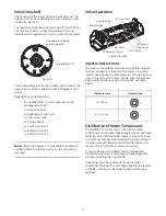
Page 16: ...erant is directed to the resin bed The hardness ions are displaced by sodium ions Regenerant draw is completed when the air check closes Slow Rinse Downflow Cycle C3a Water flow moves the regenerant through the resin at a specific rate and rinses to the drain The resin is regenerated Repressurization Cycle C4 Pressure is balanced in the valve before continuing the regeneration Fast Rinse Downflow ...

Page 17: ... onto the end of the injector The valve injector size is based on water pressure of 20 to 60 psi and uses an injector with 5 bumps If water pressure exceeds 60 psi we recommend using a 4 bump size see table below Disinfection of Water Conditioners The materials of construction of the modern water conditioner will not support bacterial growth nor will these materials contaminate a water supply Duri...

Page 18: ...imum of 8 hours depending on the installation The controller will continue to keep time and day in dynamic memory while there is no AC power The controller will not track water usage on volumetric demand controls in the event of a power failure All programmed parameters are stored in the static memory and will not be lost in the event of a power failure These settings are maintained separately fro...

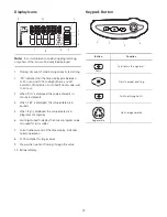
Page 19: ...crements 4 When LBS is displayed the value entered is in pounds 5 When Kg is displayed the value entered is in kilograms or kilograins 6 Four digits used to display the time or program value Also used for error codes 7 Colon flashes as part of the time display Indicates normal operation 8 X100 multiplier for large values 9 Shows when water is flowing through the valve 10 Banner display Keypad Butt...

Page 20: ...kwash purge and refill and brine draw to actually take place Make sure control power source is plugged in The transformer should be connected to a non switched power source Programming Overview The AvantaPure controller is designed to operate by setting the Time of Day Day of the Week and the Hardness The remaining settings are set at the factory using a Model Number The buttons on the keypad are ...

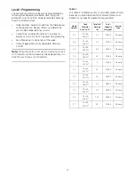
Page 21: ...clock a PM indicator will illuminate when the displayed time is in the PM hours There is no AM indicator Table 1 This table is for reference only Your model number should be set by an AvantaPure Water Treatment Professional based on your specific application requirements Model Number Tank Diameter Resin Cu Ft Total Salt Dosage lbs Total Capacity Kilograins Injector Type 47 10 x 40 1 00 Ft3 2 5 10 ...

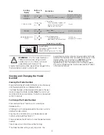
Page 22: ...lashing The Model Number setting is very important The AvantaPure controller software includes additional Model Numbers that operate other AvantaPure valve types If the Model number is set incorrectly an ERROR 3 could be displayed when advancing the valve through the regeneration cycles The valve will not function properly The control Model Number must be selected from Table 1 in this service manu...

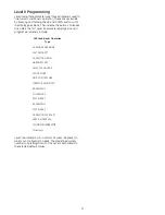
Page 23: ...l II program parameters include Level II parameters will in almost all cases be preset to meet your configuration needs The predefined system number will preprogram all of the Level II parameters to the selected default values 269 Conditioner Operation Type CALENDAR OVERRIDE SALT AMOUNT CAPACITY K GRAIN HARDNESS GPG SELECT LANGUAGE CLOCK MODE UNITS OF MEASURE INJECTOR SELECTION BACKWASH 1 SLOW RIN...

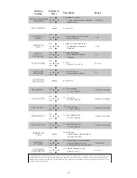
Page 24: ... regenerations 1 8 12 or 24 0 1 6 Clock Select 12 hr or 24 hr 7 Units of Measure Select English or Metric 8 View Only 9 First Backwash DO NOT CHANGE Use factory settings Use factory settings 12 Second Backwash DO NOT CHANGE 10 Slow Rinse DO NOT CHANGE 11 First Fast Rinse DO NOT CHANGE Use factory settings Use factory settings 13 Second Fast Rinse DO NOT CHANGE Use factory settings 14 Valve Type Di...

Page 25: ...EL NUMBERa See Salt Capacity Table X DAYS SINCE REGENERATION 0 to 255 days X PEAK FLOW RATE DAY AND TIME Language Clock Mode Dependant X PEAK FLOW RATE GPMa 0 to 47 GPM X WATER TREATED TODAY GAL 0 to 65536 gal X WATER SINCE REGENERATION GAL 0 to 65536 gal X SUNDAY AVERAGE USAGE GAL 0 to 65536 gal X MONDAY AVERAGE USAGE GAL 0 to 65536 gal X TUESDAY AVERAGE USAGE GAL 0 to 65536 gal X WEDNESDAY AVERA...

Page 26: ...ion The control will display an hourglass indicating that the motor and camshaft are turning The control also displays the total regeneration time remaining When the control reaches the repressurize cycle C4 the hourglass is no longer displayed and the motor will turn off Pressing the SET button will display the time remaining for the current cycle 4 Press and release SET and UP simultaneously to ...

Page 27: ...ch the bottom of the tank until all air bubbles have been purged from the line and the water level is rising C Let the water flow down the line to the tank only until the rising water is vis able D Simultaneously press and release the SET and UP buttons to advance to the Brine Make up cycle After the Brine Make up cycle is reached press the SET and UP buttons to advance to the Brine Draw Slow Rins...

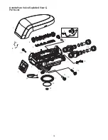
Page 28: ...28 AvantaPure Valve Exploded View Parts List BYPASS BYPASS 1 2 3 4 5 6 7 8 9 10 11 12 13 14 15 16 17 18 19 12 21 22 23 20 24 ...

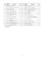
Page 29: ...ank Ring 1 1237402 Cam Valve Green 269 18 1010154 O Ring Tank 1 7 4000584 Cover AvantaPure Lt Gray Indoor 1 19 1010428 O Ring Riser Tube 1 4000585 Skirt AvantaPure Lt Gray 1 20 1002449 Valve Drain Connection Fitting Elbow 3 4 NPT x 1 2 Hose Tubing 1 1240601 Cover AvantaPure Lt Gray Outdoor 1 1041174 Valve Disc Kit 1 8 1000811 Transformer 120 VAC 60 Hz N American Plug 1 21 1040930 1265 Bypass Valve...

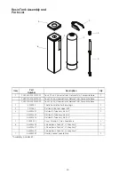
Page 30: ...al Inlet Natural Color Composite Base 2 4000585 Shield Decorative Performa Logix 1 3 1035682 Distributor Basket Upper 269 1 4 GL4001422 Distributor Tube Assy ABS 40 1 GL4001423 Distributor Tube Assy ABS 44 GL4001424 Distributor Tube Assy ABS 54 5 CH20902 2 Cover Shroud Lt Gray AvantaPure 1 6 GL4001456 Shroud Resin Tank 40 Lt Gray Assy 1 GL4001457 Shroud Resin Tank 44 Lt Gray Assy GL4001407 Shroud ...

Page 31: ...ine Well 4 Dia Caplug STP 4 1 6 CH15064 1 Brine Float w One Grommet As Purchased 1 7 CH15063 2 Air Check Assembly 1 8 BR10332 Tubing Insert Brass 2 9 CH20774 Overflow Fitting Assembly 1 CH15031 1 Overflow Elbow 1 CH15031 2 Overflow Nut 1 CH16331 Gasket 1 CH20731 1 Polypro Washer 1 10 GL4001454 Brine Tank Cover 1 11 GL4001453 Cover Square AvantaPure 1 GL4001448 Label WQA AvantaPure 1 GL40011447 Lab...

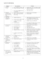
Page 32: ...erify that motor wire harness is connected to motor and controller module Verify that optical sensor is connected and in place Verify that motor gear has engaged cam gear If everything is connected try replacing in this order Wire harness Motor Optical sensor Controller If camshaft is turning for more than five minutes to find Home position Verify that optical sensor is in place and connected to w...

Page 33: ...orrect setting according to instructions b Remove restriction c Clean injector and screen d Replace injector and cap Contact dealer e Remove foreign matter from disc and check disc for closing by pushing in on stem Replace if needed Contact dealer f Put control momentarily into brine refill Replace or repair air check if needed Contact dealer 5 Control will not regenerate automatically a AC adapte...

Page 34: ... Turbine should spin freely If not replace meter Contact dealer 13 Run out of conditioned water between regenerations a Improper regeneration b Incorrect regenerant setting c Incorrect hardness or capacity settings d Water hardness has increased e Restricted meter turbine rotation due to foreign material in meter a Repeat regeneration making certain that correct regenerant dosage is used b Set P6 ...

Page 35: ...35 ...

Page 36: ... 2011 Pentair Residential Filtration LLC P N 4001404 Rev A JE11 Pentair Residential Filtration LLC 5730 North Glen Park Road Milwaukee WI 53209 4454 USA 262 238 4400 Phone 262 238 4402 Fax ...

Reviews: